Display substrate and display device

A display substrate, the same technology, applied in the direction of electrical components, circuits, organic semiconductor devices, etc., can solve the problems of brightness reduction, color shift, color coordinate shift, etc., achieve the improvement of viewing angle characteristics, improve the problem of color shift, and improve the large viewing angle The effect of brightness problems

Active Publication Date: 2018-10-23
BOE TECH GRP CO LTD
View PDF3 Cites 24 Cited by
  • Summary
  • Abstract
  • Description
  • Claims
  • Application Information

AI Technical Summary

Problems solved by technology

Although the microcavity structure can play a certain role in the selection, narrowing, and strengthening of light sources, it has the advantages of improving the chromaticity of OLED devices, enhancing the emission intensity of specific wavelengths, and changing the luminous color of OLED devices to a certain extent; However, due to the strong selective effect of the microcavity effect on the wavelength, the OLED device will have problems such as brightness reduction and color shift (ie color shift, color coordinate shift) at different viewing angles (view angle), which is unfavorable for display devices. the elements of

Method used


Image

  • Display substrate and display device
  • Display substrate and display device
  • Display substrate and display device

Examples


Embodiment 1

[0049] This embodiment provides a display substrate. On the basis of introducing an optical microcavity into the OLED device in the display substrate, the structure of the microcavity is further improved. By combining light-emitting points of the same color light, the OLED device is narrowed At the same time, it can obtain better brightness and more stable color coordinates at different viewing angles.

[0050] The OLED display substrate includes periodically arranged pixels, each pixel includes light-emitting units of different colors, and the light-emitting units of each color use OLED devices with different microcavities. Here, each light emitting unit can be disposed above the base substrate, which is the same as the prior art, and will not be described in detail here.

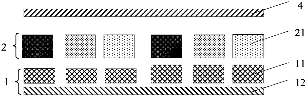
[0051] Such as figure 2 As shown, the display substrate includes a plurality of pixels arranged in an array, each pixel includes: an organic electroluminescent device for emitting light of different colo...

Embodiment 2

[0074] This embodiment provides a display substrate. On the basis of introducing an optical microcavity into the OLED device in the display substrate, the structure of the microcavity is further improved. By combining light-emitting points of the same color light, the OLED device is narrowed At the same time, it can obtain better brightness and more stable color coordinates at different viewing angles.

[0075] The OLED display substrate includes periodically arranged pixels, and the pixels include light-emitting units of different colors, and the light-emitting units of each color adopt OLED device structures with different microcavities. Here, each light emitting unit can be disposed above the base substrate, which is the same as the prior art, and will not be described in detail here.

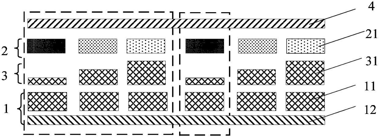
[0076] Different from Example 1, as Figure 4 As shown, the display substrate in this embodiment further includes a functional layer between the anode 1 and the cathode 4, and the functiona...

Embodiment 3

[0093] This embodiment provides a display substrate. On the basis of introducing an optical microcavity into the OLED device in the display substrate, the structure of the microcavity is further improved. By combining light-emitting points of the same color light, the OLED device is narrowed At the same time, it can obtain better brightness and more stable color coordinates at different viewing angles.

[0094] Different from Example 1 or Example 2, as Image 6 As shown, in the display substrate in this embodiment, the light-emitting layers 2 of the organic electroluminescent devices of the same color light in adjacent pixels have different thicknesses. By improving the light-emitting layer 2, microcavities with different optical lengths are formed, and then by combining the light-emitting points of the same color light in adjacent pixels, the brightness viewing angle and chromaticity viewing angle characteristics of the display substrate based on this structure are greatly im...


PUM


Abstract

The invention belongs to the display technology field and especially relates to a display substrate and a display device. The display substrate comprises a plurality of pixels which are arranged in anarray mode. Each pixel comprises an organic electroluminescence device used for emitting different colored light. The organic electroluminescence device at least comprises an anode, a cathode, and alight emitting layer between the anode and the cathode. The organic electroluminescence devices possessing a same colored light in the adjacent pixels have microcavities with different optical lengths. And / or, the organic electroluminescence device with at least one monochromatic light in the same pixel has the microcavities with the different optical lengths. By using the display substrate, through adjusting the optical lengths of the microcavities, a large visual angle brightness problem is solved.

Description

technical field [0001] The invention belongs to the field of display technology, and in particular relates to a display substrate and a display device. Background technique [0002] Research has found that the minimum angle between the two points that can be distinguished by the human eye is about 1' to the center of the pupil of the eye, which is the "resolving power" of the human eye. Assuming that there are two points 1cm apart on the screen of the mobile phone, the farther the paper is from the eyes, the smaller the angle between the two points to the eyes. Under normal circumstances, when a person uses a mobile phone, the distance between the eyes is 25cm, and the two points that can be distinguished are more than 0.1mm apart. When two points with higher brightness are resolved, the distance will increase significantly. If the resolution of the mobile phone is QHD (Quarter High Definition, a kind of screen resolution, which is a quarter of FULL HD 1920×1080), the dista...

Claims


Application Information

Patent Timeline
Patent Type & Authority Applications(China)
IPC IPC(8): H01L27/32H01L51/50H01L51/52
CPCH10K59/30H10K59/00H10K59/122H10K59/121H10K50/15H10K50/828H10K59/35H10K50/818H10K50/852H10K2102/3026H10K2102/351H10K59/351H10K59/12H10K50/805H10K50/85H10K2102/101H10K59/353H10K50/16H10K50/171
Inventor 樊星闫光张林涛刘政
Owner BOE TECH GRP CO LTD
Why Eureka
Try Eureka