
A detection device and portable electronic equipment with the detection device

A technology of electronic equipment and detection devices, which is applied in the direction of measuring devices, measuring electricity, and measuring electrical variables, etc., can solve the problems of reducing the ideal use time of equipment and the waste of power energy of detection devices, and achieve the effect of increasing normal use time and reducing power consumption

Active Publication Date: 2021-03-30
SHENZHEN INSHOW TECH CO LTD
View PDF19 Cites 0 Cited by
  • Summary
  • Abstract
  • Description
  • Claims
  • Application Information

AI Technical Summary

Problems solved by technology

[0003] At present, the detection devices of electronic equipment are in the connected state when the electronic equipment is in normal use, and continue to consume power to detect the state of the equipment. When the cover or other important parts fall off, the electrical connection is disconnected, and the corresponding detection module in the equipment After detecting the power-off signal, perform corresponding operations on the electronic equipment, so that during the use of the equipment, the continuous power consumption of the detection device causes waste of electric energy and reduces the ideal use time of the equipment

Method used


Image

  • A detection device and portable electronic equipment with the detection device
  • A detection device and portable electronic equipment with the detection device
  • A detection device and portable electronic equipment with the detection device

Examples


Embodiment 1

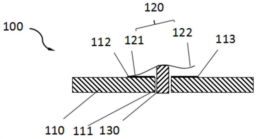
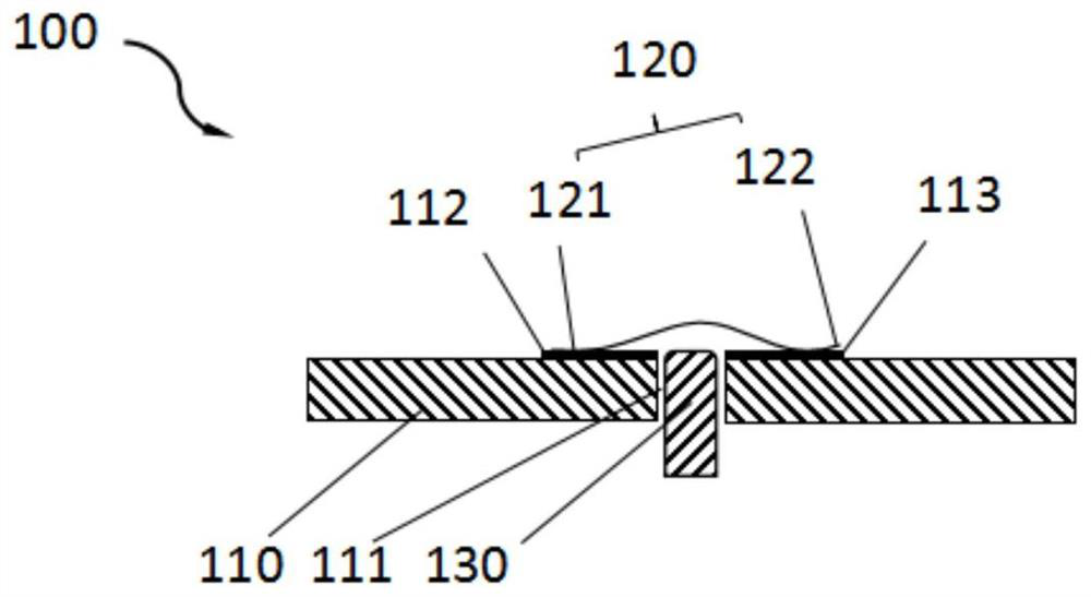
[0025] like figure 1 , figure 2 As shown, the present invention provides a detection device 100, the detection device 100 includes a circuit board 110, an elastic switch, a detected part 130 and a detection module, the circuit board 110 is provided with a through hole 111, the through hole 111 The two opposite sides are respectively provided with a first conductive position 112 and a second conductive position 113; the elastic switch part includes a conductive contact part, and the two ends of the conductive contact part are forced to connect with the first conductive position 112 and the second conductive part respectively through the elastic reset of the elastic switch part. The two conductive positions 113 are contacted and connected to realize the conductive connection between the first conductive position 112 and the second conductive position 113, and the detected part, the detected part and the elastic switch part are abutted and connected, so that the elastic switch p...

Embodiment 2

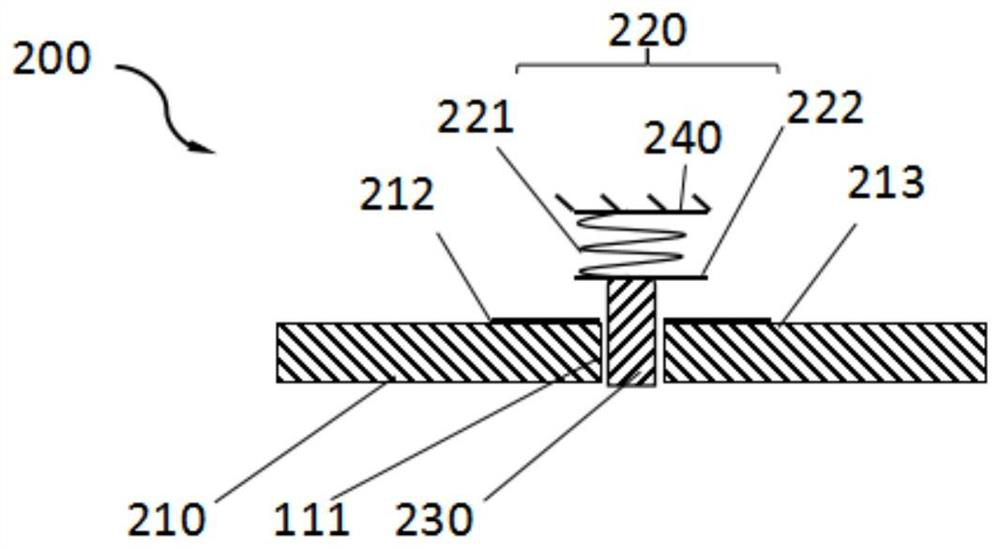
[0028] like image 3 , Figure 4As shown, it is the second embodiment of the detection device provided by the present invention. The detection device 200 includes a circuit board 210, an elastic switch 220, a detected part 230 and a detection module. The difference is that the detection device 200 also includes Bracket 240, the elastic switch 220 includes a first spring 221 and a conductive member 222, the two ends of the first spring 221 are respectively fastened to the bracket 240 and the conductive member 222, and the two ends of the conductive member 222 are respectively connected to the first conductive position 212 Corresponding to the second conductive position 213, the elastic return of the first spring 221 forces the two ends of the conductive member 222 to contact and connect with the first conductive position 212 and the second conductive position 213 respectively; when the detected part 230 passes through a rod structure When the first spring 221 is compressed and...

Embodiment 3

[0031] like Figure 5 , Figure 6 As shown, it is the third embodiment of the detection device provided by the present invention. The detection device 300 includes a circuit board 310, an elastic switch part 320, a detected part 330 and a detection module. The difference is that the elastic switch part 320 includes Second spring 321, connecting rod 322 and conductive rod 323, one end of connecting rod 322 passes through hole 311 and is connected with conductive rod 323 tightly, forms T-shaped structure, and the two ends of conductive rod 323 are connected with the first conductive position 312 and the second conductive rod 323. The two conductive positions 313 are arranged correspondingly, the second spring 321 is sleeved on the connecting rod 322, and the two ends of the second spring 321 are respectively connected to the circuit board 310 and the end of the connecting rod 322 away from the conductive rod 323, the elasticity of the second spring 321 Resetting forces the two ...


PUM


Abstract

The invention provides a detection device and a portable electronic device with the detection device. The detection device includes a circuit board, an elastic switch, a detected part and a detection module. The circuit board is provided with a through hole, and the two holes of the through hole The opposite sides are respectively provided with a first conductive position and a second conductive position. The elastic switch part includes a conductive contact part. The elastic switch part is elastically deformed or elastically reset by the detected part, thereby determining the two ends of the conductive contact part. Whether it is in contact with the first conductive bit and the second conductive bit at the same time to realize or disconnect the conductive connection between the first conductive bit and the second conductive bit, the detection module is electrically connected with the circuit board to detect the first conductive The use of the detection device can effectively reduce the power consumption between the conductive position and the second conductive position, and the portable electronic equipment with the detection device can effectively reduce the power consumption of the portable electronic equipment and increase its normal use time.

Description

technical field [0001] The invention relates to the field of electronic products, in particular to a detection device and a portable electronic device with the detection device. Background technique [0002] In the modern information society with highly developed data communication systems, portable electronic devices are widely used in various fields, such as mobile phones, notebook computers, etc. The maintenance of portable electronic devices is also an important part of their design and manufacture, but abnormal maintenance and Opening the cover may cause damage to important mechanisms of electronic equipment. Therefore, the detection device used to prevent electronic equipment from being opened due to abnormal maintenance is an important safety mechanism for electronic equipment. The equipment performs corresponding operations to protect the electronic equipment. In addition, this type of detection device can not only be used in the detection of opening the cover, but a...

Claims


Application Information

Patent Timeline
Patent Type & Authority Patents(China)
IPC IPC(8): G01R31/54G01R31/50
CPCG01R31/50H05K1/0275H05K2201/09063H05K2201/10053H05K2201/0311H05K1/0268
Inventor 曹琛李凤雷
Owner SHENZHEN INSHOW TECH CO LTD
Learn More