Motor

一种马达、传感器的技术,应用在马达领域,能够解决不能电动马达薄型化等问题,达到同轴精度高的效果

Active Publication Date: 2018-10-23
NIDEC CORP
View PDF5 Cites 6 Cited by
  • Summary
  • Abstract
  • Description
  • Claims
  • Application Information

AI Technical Summary

Problems solved by technology

Therefore, there is a problem that the overall thickness of the electric motor cannot be reduced

Method used


Image

  • Motor
  • Motor
  • Motor

Examples


Embodiment Construction

[0013] A motor 1 according to an embodiment of the present invention is mounted in, for example, an electric brake booster 1 . The electric brake booster 8 is used for braking operations of vehicles such as automobiles.

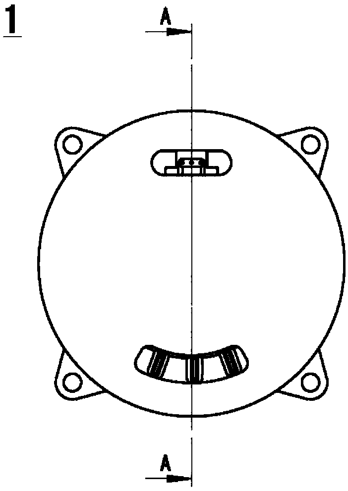
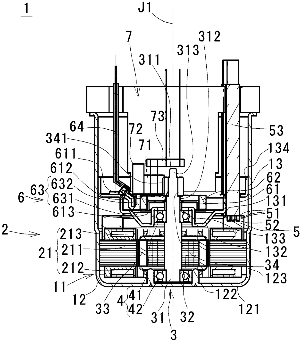
[0014] figure 1 is a plan view showing the motor 1, figure 2 is in figure 1 The longitudinal sectional view of the motor 1 is cut at the position of A-A. exist image 3 In , a cross section on a plane including the central axis J1 of the motor 1 is shown. The motor 1 is a 3-phase AC motor driven by 3-phase AC current.

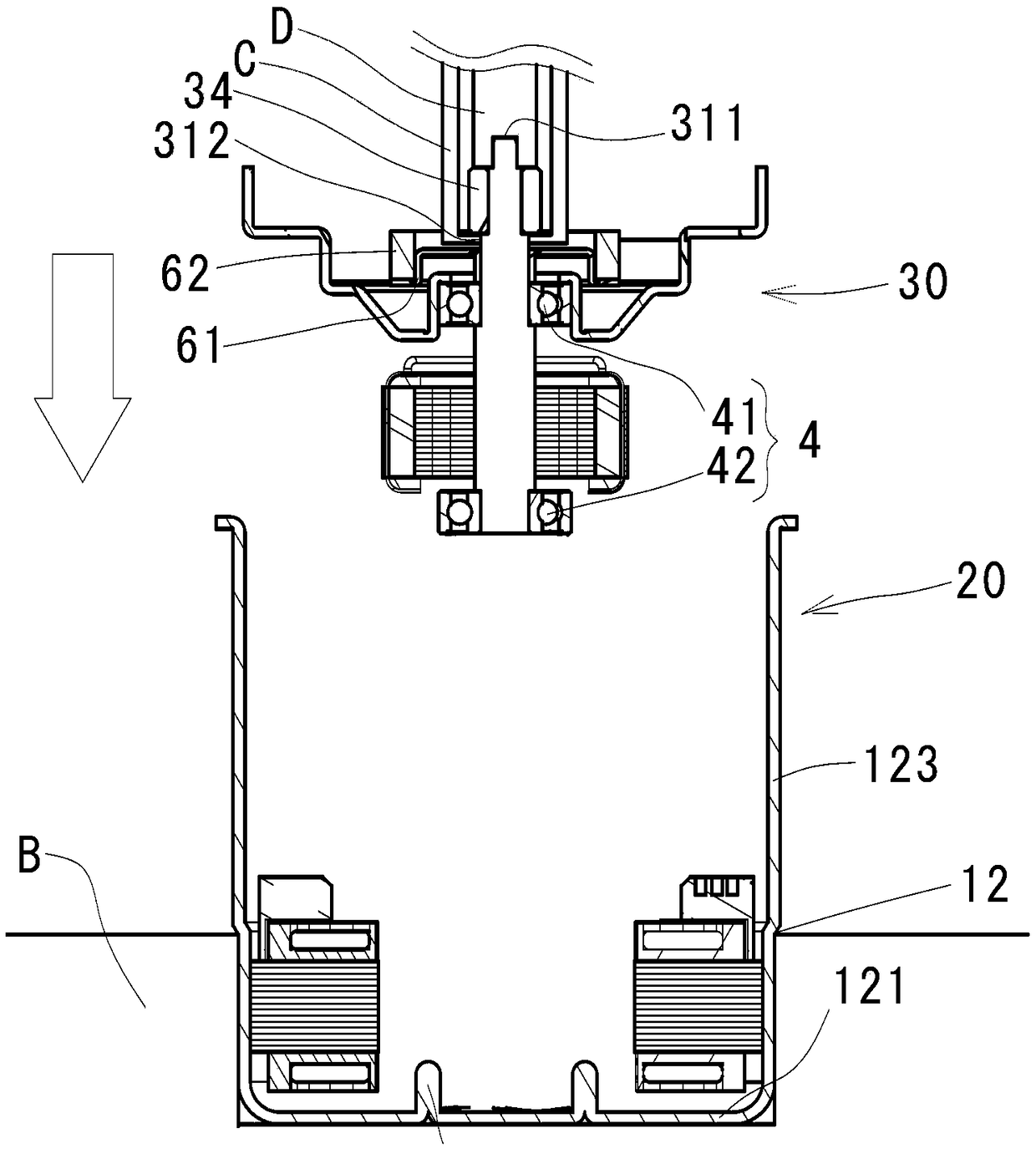
[0015] Such as image 3 As shown, the motor 1 is an inner rotor type motor, which includes: a stator part 2; a rotor part 3; a bearing mechanism 4, which supports the rotor part 3 so as to be rotatable around the central axis J1 relative to the stator part 2; unit 5 that connects the coil 213 of the stator part 2 with an external power source; and a sensor 6 that magnetically detects the angular position of the rotor core 32 of the rot...


PUM


Abstract

An electric motor provided with: a rotor part having a shaft, a rotor magnet, a sensor yoke positioned axially upward from the rotor magnet, a sensor magnet supported by the sensor yoke, and an inputgear having a gear part for transmitting torque to outside; an armature positioned radially outward of the rotor magnet; a bearing mechanism for rotatably supporting the rotor part; a housing for covering the armature, the rotor part, and the bearing mechanism; and a rotary detection sensor facing the sensor magnet, the rotary detection sensor detecting rotation of the rotor part. The housing hasa bottom part, and includes a housing main unit that supports the armature, and a bearing holder that supports a first bearing. The rotary detection sensor is arranged on the upper part of the bearingholder. The shaft has a top surface positioned axially upward and radially inward from the gear part, and has an exposed part that is exposed in regions axially downward from the gear part, and axially upward from the senor yoke.

Description

technical field [0001] The invention relates to a motor. Background technique [0002] Conventionally, there is known a device that is mounted on an automobile and uses a ball screw to convert rotational motion of a motor into linear motion for input. For example, Japanese Patent Application Laid-Open No. 2007-187262 discloses an electric actuator that converts rotation of an electric motor into linear motion by means of a ball screw mechanism, thereby causing an input shaft to execute a predetermined linear motion. [0003] Patent Document 1: Japanese Patent Laid-Open No. 2007-187262 Contents of the invention [0004] The problem to be solved by the invention [0005] However, in the structure of Patent Document 1, the electric motor itself is in the vertical direction in the axial direction, so the bearing, the resolver rotor and the resolver stator must be arranged at different positions in the axial direction, and the resolver rotor and the resolver must be ensured. ...

Claims


Application Information

Patent Timeline
Patent Type & Authority Applications(China)
IPC IPC(8): H02K29/08H02K7/116H02K15/16
CPCH02K29/08H02K15/16H02K7/116H02K11/215H02K5/1732H02K5/04H02K15/022
Inventor 福永庆介
Owner NIDEC CORP
Why Eureka
Try Eureka