Miniature bending machine for machining small thin-wall part

A technology for thin-walled parts and bending machines, applied in metal processing equipment, feeding devices, manufacturing tools, etc., can solve the problem of increasing the cost of product molds, inconvenient processing of thin and small sheet metal parts, affecting product production efficiency, etc. problems, to achieve the effect of ensuring quality and pass rate, shortening production preparation time, and simple and easy force control

Active Publication Date: 2018-10-26
SICHUAN JIUZHOU ELECTRIC GROUP
View PDF4 Cites 2 Cited by
  • Summary
  • Abstract
  • Description
  • Claims
  • Application Information

AI Technical Summary

Problems solved by technology

[0002] At present, the processing of thin and small sheet metal parts in China usually uses special molds for stamping and bending machine processing; in recent years, with the diversification, complexity and precision of product structures, more and more products use small sheet metal parts. Metal parts, and ordinary bending machines must use special molds to process such thin and small sheet metal parts. When there are more types of products and the batch size is not large, the cost of product molds will be seriously increased. and affect product productivity
[0003] Most of the existing bending machines are me

Method used


Image

  • Miniature bending machine for machining small thin-wall part
  • Miniature bending machine for machining small thin-wall part
  • Miniature bending machine for machining small thin-wall part

Examples


Embodiment Construction

[0024] In order to make the object, technical solution and advantages of the present invention clearer, the present invention will be further described in detail below in conjunction with the accompanying drawings and embodiments. It should be understood that the specific embodiments described here are only used to explain the present invention, not to limit the present invention.

[0025] A micro bending machine for processing small thin-walled parts of the present invention will be explained in detail below in combination with specific structures and principles.

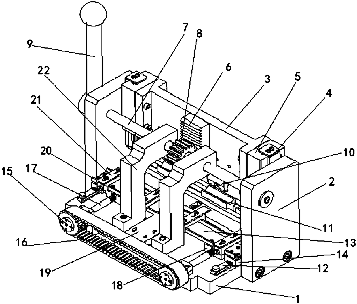
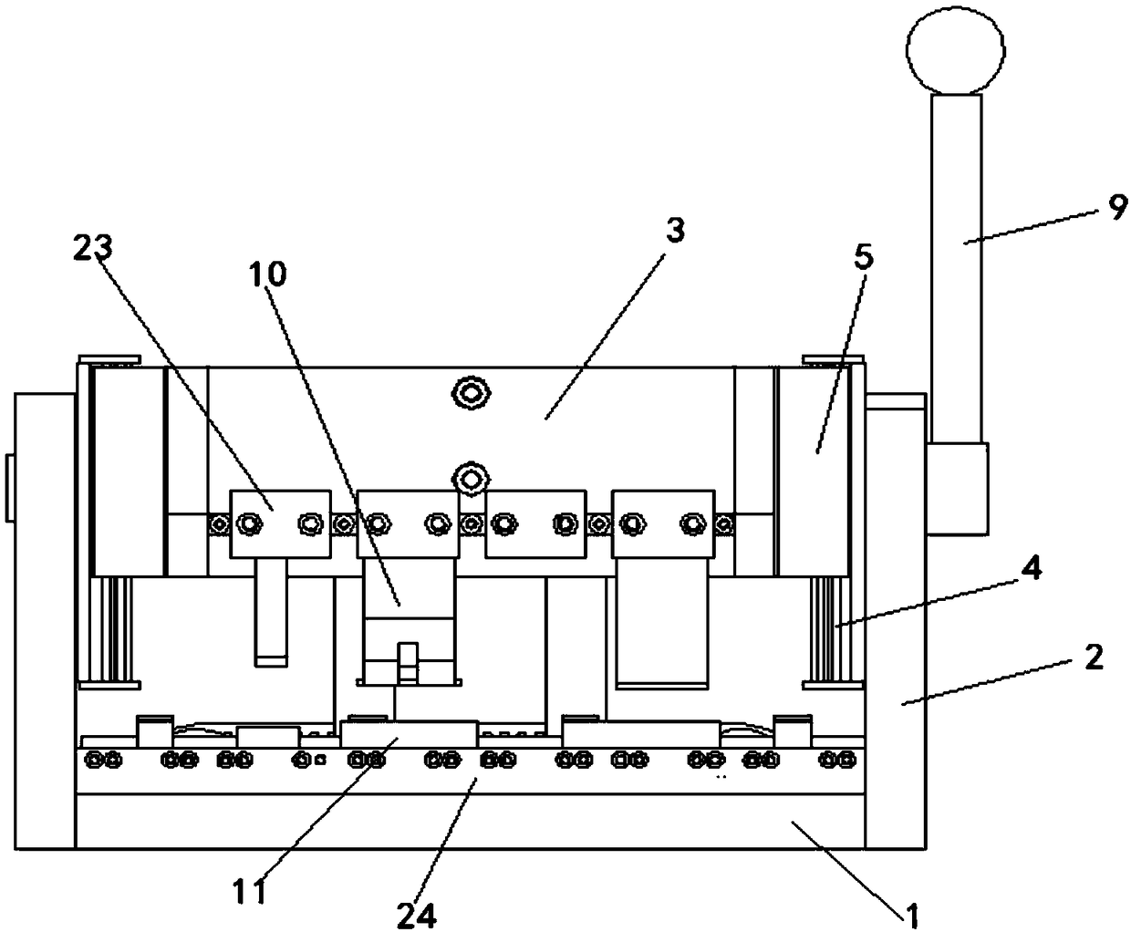
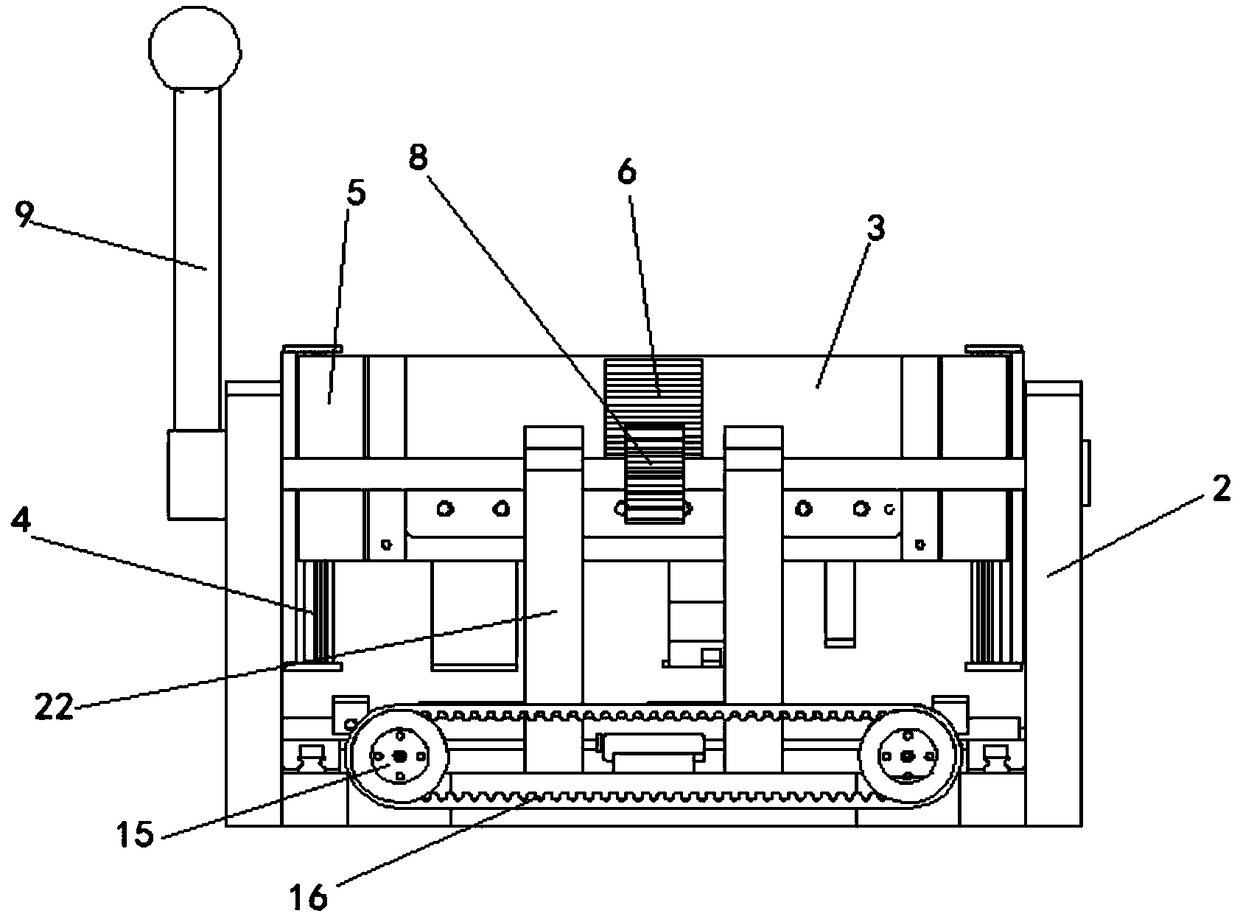
[0026] A miniature bending machine for processing small thin-walled parts, such as figure 1 , figure 2 , image 3 , Figure 4 and Figure 5 shown. It includes the base plate 1, the side plates 2 distributed on both sides of the base plate 1 perpendicular to the base plate 1, the guide rails 4 installed on the inside of the side plates 2 on both sides, and the guide rail plate 5 that is distributed outside the...


PUM


Abstract

The invention discloses a miniature bending machine for machining a small thin-wall part, and belongs to the technical field of bending devices. The miniature bending machine comprises a bottom plate,side plates, guide rails, guide rail plates and a transverse plate; the side plates are distributed on the two sides of the bottom plate and are perpendicular to the bottom plate, the guide rails areinstalled on the side plates on the two sides, the guide rail plates which are distributed outside the guide rails and enable the guide rails to be inlaid and can slide relative to the guide rails, and the transverse plate is installed between the two guide rail plates; an upper profiling mould is arranged on the transverse plate, and a transmission rack is arranged on the inner side face of thetransverse plate; the miniature bending machine further comprises a shaft and a force arm rod, wherein the shaft is inlaid in the two side plates and can rotate relative to the side plates, the forcearm rod is connected to the shaft and can drive the shaft to rotate, and a gear corresponding to the transmission rack is arranged on the shaft; and a concave mould corresponding to the upper profiling mould is arranged on the bottom plate. According to the miniature bending machine, the bending machine is manually driven by the force arm, the longitudinal manual feeding control is realized only by the gear-rack meshing transmission, and the force degree is simple and easy to control; and the bending machine is used for various special-shaped and small sheet metal parts, only the universal upper profiling mould and the universal concave mould need to be manufactured to be directly processed, and the cost is low.

Description

technical field [0001] The invention belongs to the technical field of bending devices, in particular to a miniature bending machine for processing small thin-walled parts. Background technique [0002] At present, the processing of thin and small sheet metal parts in China usually uses special molds for stamping and bending machine processing; in recent years, with the diversification, complexity and precision of product structures, more and more products use small sheet metal parts. Metal parts, and ordinary bending machines must use special molds to process such thin and small sheet metal parts. When there are more types of products and the batch size is not large, the cost of product molds will be seriously increased. And affect the production efficiency of the product. [0003] Most of the existing bending machines are mechanical or hydraulic bending machines. Because of their large bending power and bending radius, it is inconvenient to process thin and small sheet me...

Claims


Application Information

Patent Timeline
IPC IPC(8): B21D5/00B21D7/06B21D43/00
Inventor 周永曾飞云
Owner SICHUAN JIUZHOU ELECTRIC GROUP
Why Eureka
Try Eureka