Phase change type radiator

A radiator and phase change technology, which is applied in the direction of aircraft, spacecraft for space flight, and devices for controlling the living conditions of space flight vehicles.

Inactive Publication Date: 2020-10-23
SHANGHAI LIZHENG SATELLITE APPL TECH CO LTD
View PDF6 Cites 1 Cited by
  • Summary
  • Abstract
  • Description
  • Claims
  • Application Information

AI Technical Summary

Problems solved by technology

There is still room for improvement in th

Method used


Image

  • Phase change type radiator
  • Phase change type radiator
  • Phase change type radiator

Examples


Embodiment Construction

[0024] The present invention will be described in detail below in conjunction with specific embodiments. The following examples will help those skilled in the art to further understand the present invention, but do not limit the present invention in any form. It should be noted that those skilled in the art can make several changes and improvements without departing from the concept of the present invention. These all belong to the protection scope of the present invention.

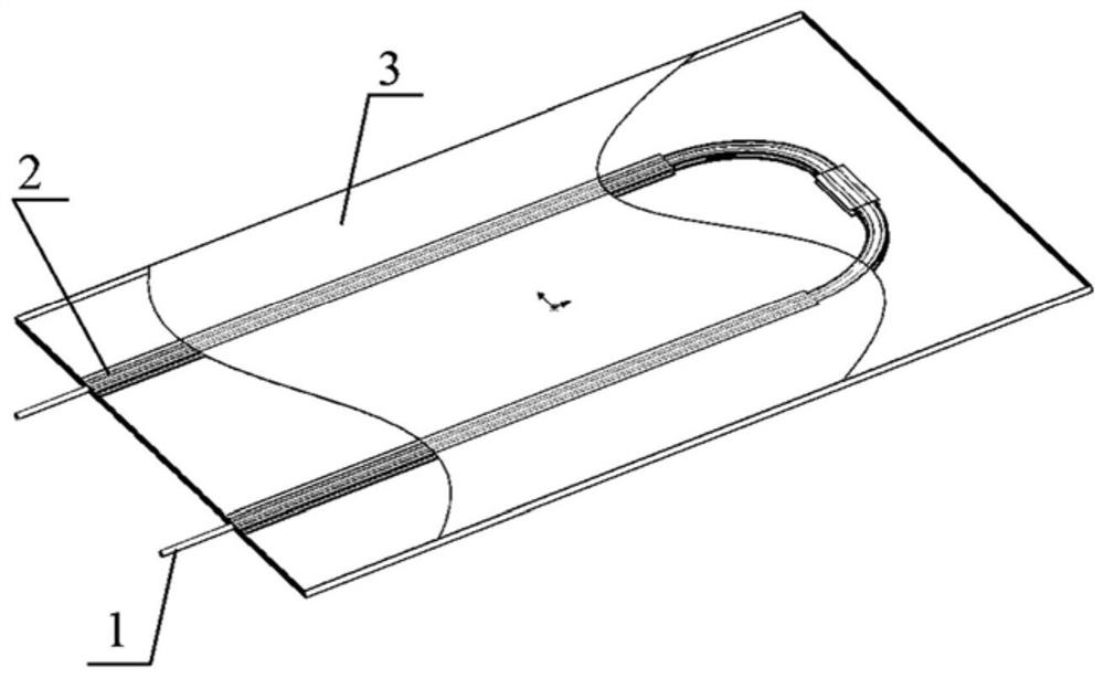
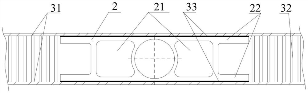
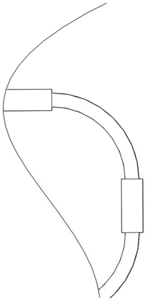
[0025] Such as Figure 1-3 , a phase change radiator provided according to the present invention, comprising: an inlet and outlet pipeline 1, a fluid pipeline 2 and a honeycomb panel 3; wherein: the fluid pipeline 2 has a phase change structure; the fluid pipeline 2 It is bent into a U-shaped structure; the inlet and outlet pipelines 1 are connected to the fluid pipeline 2; the fluid pipeline 2 is buried inside the honeycomb panel 3 .

[0026] Preferably, the inlet and outlet pipeline 1 includes: an in...


PUM


Abstract

The invention provides a phase change type radiator. The phase change type radiator comprises an inlet and outlet pipeline (1), a fluid pipeline (2) and a honeycomb plate (3). The fluid pipeline (2) is provided with a phase change structure; the fluid pipeline (2) is bent into a U-shaped structure; the inlet and outlet pipeline (1) is connected with the fluid pipeline (2); and the fluid pipeline (2) is buried in the honeycomb plate (3). The invention provides the phase change type radiator which is composed of the fluid pipeline with a phase change structure, a honeycomb plate, and the inlet and outlet pipeline, the inlet and outlet pipeline is located at the two ends of the fluid pipeline with the phase change structure, and the upper surface and the lower surface of the fluid pipeline with the phase change structure are connected with an inner surface skin of the honeycomb plate.

Description

technical field [0001] The invention relates to the technical field of spacecraft thermal control, in particular to a phase change radiator. Background technique [0002] With the development of aerospace technology, the load of the spacecraft is increasing, the power consumption is gradually increasing, and the requirements for the temperature control of the spacecraft are also getting higher and higher. The traditional cooling technology has been unable to meet the demand for large cooling capacity. The flexible heat dissipation of efficient two-phase loop technology becomes the key. The radiator used in the traditional two-phase circuit technology is to directly weld the smooth circular tube to the radiant plate or rivet it to the radiant plate in a serpentine manner. This method has many times of bending, long pipeline, large flow resistance, and radiation at the same time. The heat dissipation capability of the radiator is also restricted by the size of the radiation p...

Claims


Application Information

Patent Timeline
IPC IPC(8): B64G1/50
CPCB64G1/503
Inventor 刘顺周日海陈辉
Owner SHANGHAI LIZHENG SATELLITE APPL TECH CO LTD
Why Eureka
Try Eureka