Radio frequency identification tag antenna applied to dense environment

A radio frequency identification tag, dense environment technology, applied in the field of wireless antennas, can solve the problems of complex structure, low power transmission coefficient of tags, etc., to achieve the effect of high bandwidth, reduced accuracy and difficulty, and high power transmission coefficient

Active Publication Date: 2020-07-31
HEFEI UNIV OF TECH
View PDF10 Cites 2 Cited by
  • Summary
  • Abstract
  • Description
  • Claims
  • Application Information

AI Technical Summary

Problems solved by technology

In the existing research, for the application of the tag antenna in a dense environment, it is still improved based on the most widely used tag antenna Alien 9662 in the existing market, and the tag antenna coupling is reduced by shortening the length of the tag antenna. Mutual impedance, so that the influence of mutual interference of tag antennas in dense environments is small, but the structure of the Yagi-Uda antenna used in it is relatively complex, and in dense environments, the power transmission coefficient of tags is still low

Method used


Image

  • Radio frequency identification tag antenna applied to dense environment
  • Radio frequency identification tag antenna applied to dense environment
  • Radio frequency identification tag antenna applied to dense environment

Examples


Embodiment 1

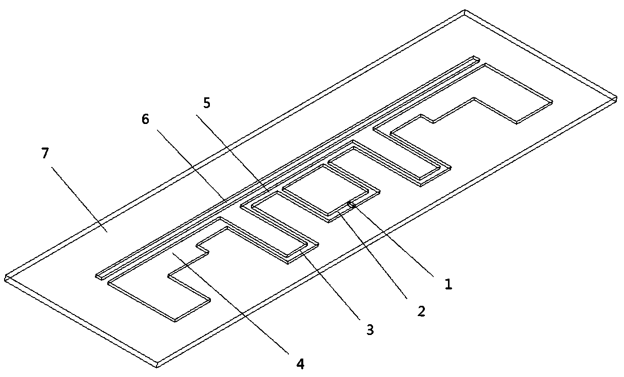
[0031] see figure 1 , a radio frequency identification tag antenna applied in a dense environment includes a tag chip 1, a loading bar 6, a radiation patch and a dielectric substrate 7, and the tag chip 1, the loading bar 6 and the radiation patch are all fixed on the dielectric substrate 7.

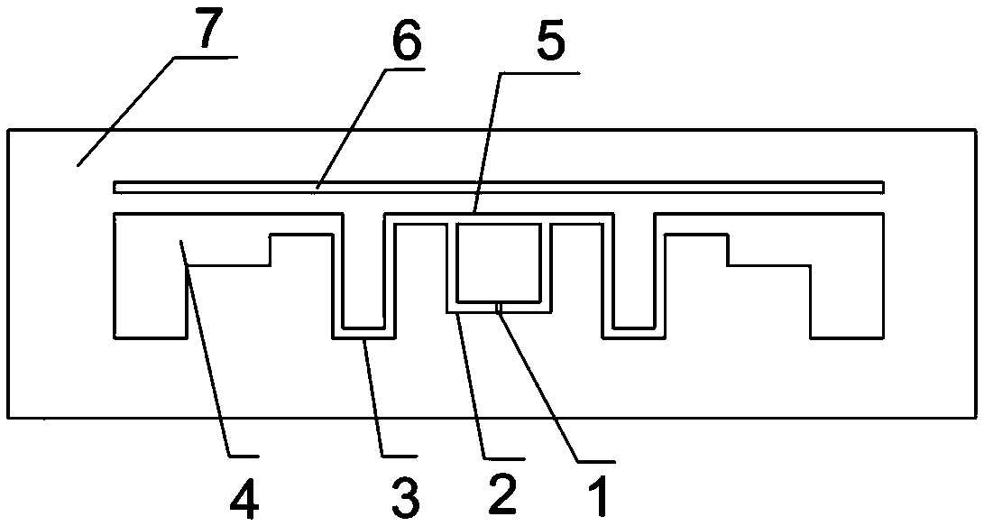
[0032] The radiation patch includes a pair of stepped radiation arms 4 , a pair of U-shaped connecting arms 3 , a pair of L-shaped connecting arms 2 and a straight connecting arm 5 . The straight connecting arm 5 is axisymmetric with respect to the symmetry axis of the tag antenna; a pair of stepped radiation arms 4, a pair of U-shaped connecting arms 3 and a pair of L-shaped connecting arms 2 are all located inside the straight connecting arm 5, and the loading bar 6 is located on the straight line The outer side of the connecting arm 5.

[0033] see figure 2 , the two ends of the straight connecting arm 5 are respectively connected to one end of a U-shaped connecting arm 3, and the ...


PUM


Abstract

The invention relates to a radio frequency identification tag antenna applied to a dense environment, which belongs to the technical field of wireless antennas. The antenna comprises a tag chip, a loading strip, a radiation patch and a dielectric substrate; the radiation patch comprises a pair of stepped radiation arms, a pair of U-shaped connecting arms, a pair of L-shaped connecting arms and linear connecting arms; the linear connecting arms are symmetrical relative to the symmetry axis of the tag antenna; the pair of stepped radiation arms, the pair of U-shaped connecting arms and the pairof L-shaped connecting arms are all located on the inner side of the linear connecting arms, and the loading strip is located on the outer side of the linear connecting arms; the loading strip is in alinear strip shape and is parallel to the linear connecting arms; when the distance between the loading strip and the radiation patch is 2 mm, the maximum power transmission coefficient of the radiofrequency identification tag antenna is greater than 0.7. When the tag antenna is located in an environment with a large distance between tags, the tag antenna also has a wide frequency band and stable performance. The radio frequency identification tag antenna is simple in structure and good in production manufacturability.

Description

technical field [0001] The invention belongs to the technical field of wireless antennas, and in particular relates to a radio frequency identification (RFID) tag antenna. Background technique [0002] Radio Frequency Identification (RFID) technology is a non-contact automatic identification technology. The electromagnetic wave signal is transmitted through the reader antenna. The tag antenna receives the electromagnetic wave signal and modulates it, and transmits the modulated signal back to the reader antenna in reverse. The process of communication. At present, with the development of technology, UHF RFID tags have gradually become the mainstream of current research due to their advantages such as easy mass production, high reading rate, long reading distance and standardized communication protocols. However, when the tags are in book management, clothing management and other scenes that require a large number of tags and the distance between the tags is very close, due ...

Claims


Application Information

Patent Timeline
Patent Type & Authority Applications(China)
IPC IPC(8): H01Q1/22H01Q1/38H01Q1/50
CPCH01Q1/2225H01Q1/38H01Q1/50
Inventor 佐磊陈昊徐相相姜学义朱良帅何怡刚李兵尹柏强
Owner HEFEI UNIV OF TECH
Why Eureka
Try Eureka