Filter apparatus for compressed air

a filter apparatus and compressed air technology, applied in the direction of dispersed particle separation, transportation and packaging, separation processes, etc., can solve the problems of pressure loss, decrease the flow rate of compressed air per hour, etc., to prevent the increase of pressure loss when the compressed air circulates, reduce the number of times of bending as a flow path, and flow large rate

Active Publication Date: 2017-08-17
FUKUHARA KK
View PDF0 Cites 2 Cited by
  • Summary
  • Abstract
  • Description
  • Claims
  • Application Information

AI Technical Summary

Benefits of technology

[0009]According to the present invention, since a flow path of compressed air passing through the filter elements is formed to extend in the upper and lower directions, upper and lower spaces can be effectively utilized even when a space for locating the filter apparatus is not large enough in the right and left directions in the compressed air pressure circuit. In addition, since the compressed air is branched in the upper and lower directions in the filter apparatus to respectively pass through the upper filter element and the lower filter element, compressed air of a large flow rate can flow per hour. Also, the compressed air passes through only one filter element in the filter apparatus, and further, the number of times of bending as a flow path is decreased as much as possible, whereby increase of pressure loss when the compressed air circulates can be prevented. In addition, the first opening or the second opening which is an inlet port or an outlet port of the compressed air is disposed at the same height since these openings include the same reference surface. Accordingly, height adjustment of piping in communication with other apparatuses becomes easy without any complex piping structure of the compressed air pressure circuit including the filter apparatus.
[0010]Further, the second opening communicates with only the lower outer space via the secondary flow path. Due to this, if the second opening is the outlet port of the compressed air (that is, when the first opening is the inlet port of the compressed air), the compressed air which has passed through the upper filter element or the lower filter element needs to move upward in the secondary flow path from the lower outer space when it is discharged from the second opening. Consequently, drain included in the compressed air drops under its own weight at this stage, whereby drain can be effectively separated from the compressed air. On the other hand, if the second opening is the inlet port of the compressed air, the compressed air firstly moves downward to flow into the lower outer space. Here, drain naturally drops. Further, since the compressed air needs to move upward when it passes through the communication flow path toward the upper outer space, most of drain can drop from the compressed air before passing through the upper filter element. Also, drain attached to the upper filter element or the lower filter element naturally drops and is discharged from the drain hole.
[0011]Moreover, by providing the inclined portion on the upper side of the body, drain generated in the upper outer space can be guided effectively to the communication flow path along the inclined portion, and the drain can be discharged from the drain hole. Moreover, if the first opening is the inlet port of the compressed air, the compressed air can be effectively guided to the lower outer space.
[0012]In addition, by forming the upper bowl and the lower bowl in the same shape to be mutually exchangeable, only a bowl with one shape needs to be formed and this can be applied to both, which improves production efficiency. In this case, the drain hole formed in the lower bowl may be utilized as a hole for communicating with a manometer or a differential pressure gauge etc. Moreover, by forming the upper filter element and the lower filter element in the same shape and further forming the upper adapter and the lower adapter for attaching the upper filter element and the lower filter element to the body in the same shape, a filter element with one shape and an adapter with one shape may be formed to be applied to both, which further improves production efficiency.

Problems solved by technology

This means that compressed air passes through the filter elements twice, which is problematic in terms of pressure loss.
In this way, the configuration of a flow path which applies pressure loss causes a decrease of the flow rate of compressed air per hour.

Method used


Image

  • Filter apparatus for compressed air
  • Filter apparatus for compressed air
  • Filter apparatus for compressed air

Examples


Embodiment Construction

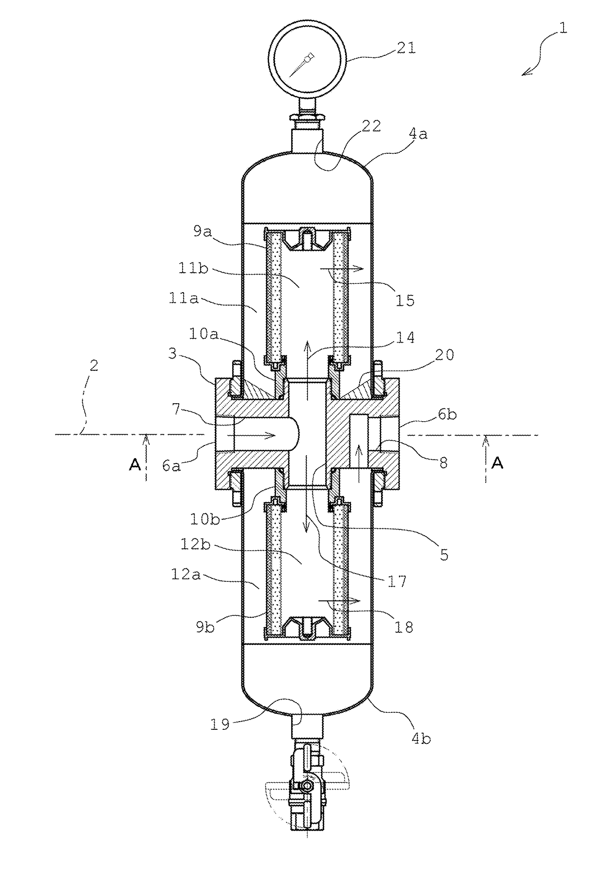
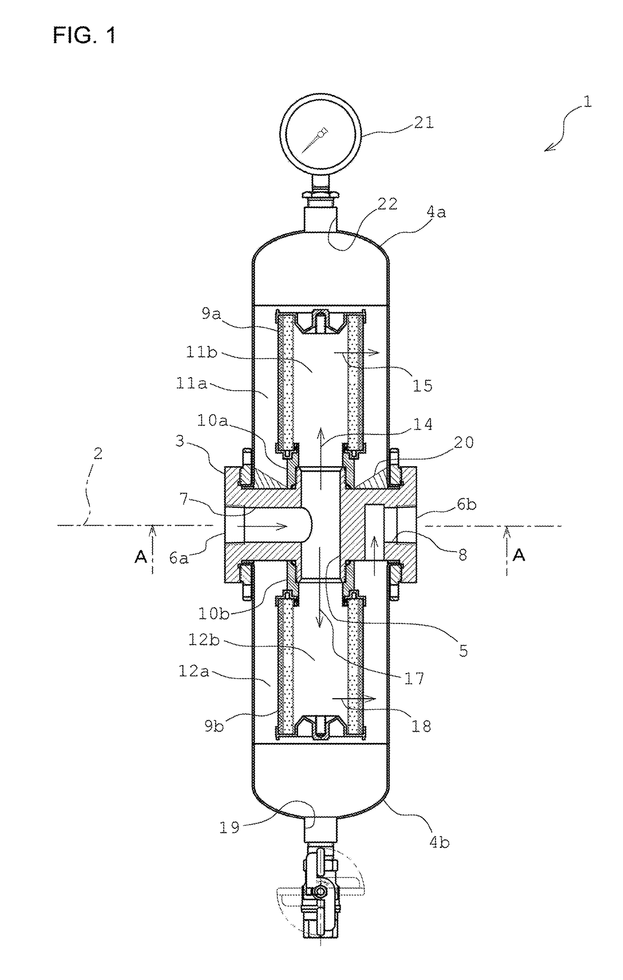
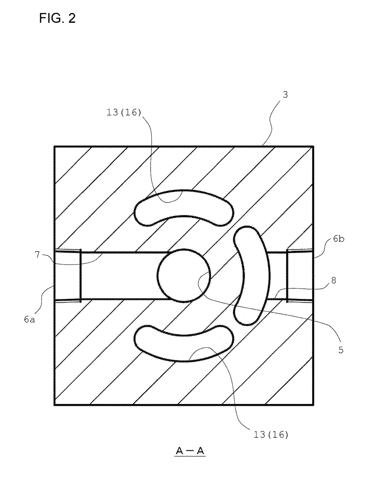
[0015]As shown in FIGS. 1 and 2, a filter apparatus for compressed air 1 according to the present invention has a horizontal reference surface 2, and is formed extending in the upper and lower directions (a vertical direction) while using this reference surface 2 as a border. More specifically, a body 3 is provided to include the reference surface 2, and to this body 3, an upper bowl 4a and a lower bowl 4b are respectively attached in the upper and lower directions. The body 3 has a substantially square pillar shape, and a penetration hole 5 piercing vertically is formed at its center. Consequently, the penetration hole 5 allows upper and lower surfaces of the body 3 to communicate. At lateral sides of the body 3, a first opening 6a and a second opening 6b are formed. These first opening 6a and second opening 6b have a substantially circular shape, and are formed at a position including the reference surface 2. For example, the first opening 6a and the second opening 6b are formed s...


PUM

PropertyMeasurementUnit
shapeaaaaaaaaaa
pressure lossaaaaaaaaaa
flow rateaaaaaaaaaa

Abstract

A compressed air filter apparatus includes a main flow path as a flow path in which compressed air should circulate, formed in a body to extend from a first opening into a penetration hole, an upper inner flow path extending from the penetration hole to an upper inner space, an upper inner and outer flow path extending from the upper inner space to an upper outer space to pass through an upper filer element, a communication flow path extending from the upper outer space to a lower outer space to pass through a communication hole, a secondary flow path extending from the lower outer space to a second opening, a lower inner flow path extending from the penetration hole to a lower inner space, and a lower inner and outer flow path extending from the lower inner space to the lower outer space to pass through a lower filter element.

Description

TECHNICAL FIELD[0001]The present invention relates to a filter apparatus for compressed air to separate impurity included therein.BACKGROUND ART[0002]In compressed air discharged from a pneumatic compressor such as an air compressor, drain which is condensed water or dust, or impurity such as lubricant oil used in the pneumatic compressor is included. Since the compressed air is thereafter used for a pneumatic apparatus such as an air gun or a cylinder, inclusion of such impurity could cause malfunction etc. of the pneumatic apparatus. That is, there is a possibility that inclusion of impurity becomes harmful to a future use of compressed air. Consequently, impurity in compressed air is separated or removed from the compressed air appropriately via an air filter (for example, see JP-A-Hei6-315615).[0003]In a compressed air pressure circuit where compressed air flows, if there is a sufficient space in a place for locating an air filter as in JP-A-Hei6-315615, it is possible to use a ...

Claims


Application Information

Patent Timeline
Patent Type & Authority Applications(United States)
IPC IPC(8): B01D46/00B01D46/24
CPCB01D46/0021B01D2279/00B01D2267/30B01D46/24B01D46/2403B01D46/60
Inventor FUKUHARA, HIROSHI
Owner FUKUHARA KK
Why Eureka
Try Eureka