

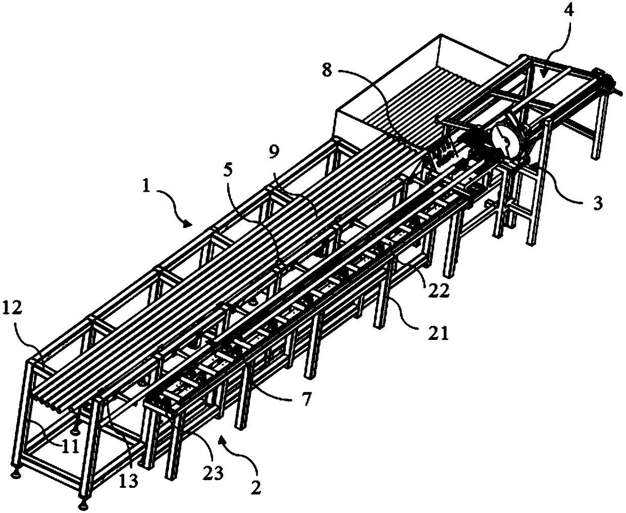
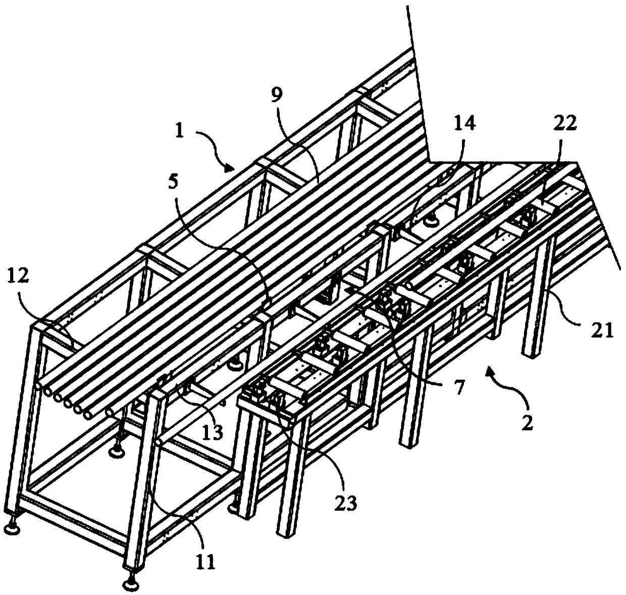
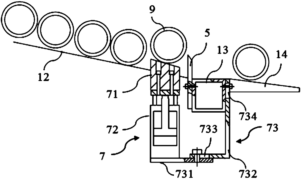
Automatic conveying and cutting equipment for pipes
A cutting equipment and automatic technology, applied in shearing machine equipment, metal processing equipment, pipe cutting devices, etc., can solve the problems of affecting cutting quality, high labor intensity, inaccurate cutting surface, etc., to achieve cutting efficiency and high cutting quality, High degree of automation and good adjustable performance
- Summary
- Abstract
- Description
- Claims
- Application Information
AI Technical Summary
Problems solved by technology
Method used
Image

Examples
Embodiment Construction
[0040] The technical solution of the present invention will be described in further non-limiting detail below in combination with preferred embodiments and accompanying drawings.
[0041] In describing the present invention, it is to be understood that the terms "upper", "lower", "front", "rear", "left", "right", "vertical", "horizontal", "top", The orientation or positional relationship indicated by "bottom", "inner", "outer", etc. are based on the orientation or positional relationship shown in the drawings, and are only for the convenience of describing the present invention, rather than indicating or implying that the referred device or element must be Having a particular orientation, or being constructed and operative in a particular orientation, should therefore not be construed as limiting the invention.
[0042] In the present invention, terms such as "installation", "connection", "connection", "fixation" and "setting" should be interpreted in a broad sense, for exampl...
PUM
 Abstract
Description
Claims
Application Information