Steel plate cutting device convenient to position accurately

A cutting device and precise positioning technology, which is applied in welding equipment, laser welding equipment, metal processing equipment, etc., can solve the problems of damaging the cutting platform and inability to accurately position steel plates, and achieve precise positioning and cutting, high practicability, and extended use The effect of longevity

Active Publication Date: 2018-10-26
芜湖立普德机械科技有限公司
View PDF7 Cites 5 Cited by
  • Summary
  • Abstract
  • Description
  • Claims
  • Application Information

AI Technical Summary

Problems solved by technology

[0003] Flame or laser cutting is often used for steel plate cutting, which uses the high temperature generated during the combustion of iron oxide to cut the steel plate placed on the cutting platform. Due to the high temperature of flame cutting, the cutting platform may be damaged, and the existing cutting device is large. Most of them cannot accurately locate the steel plate, therefore, those skilled in the art provide a kind of steel plate cutting device that is convenient for accurate positioning, to solve the problems raised in the above-mentioned background technology

Method used


Image

  • Steel plate cutting device convenient to position accurately
  • Steel plate cutting device convenient to position accurately
  • Steel plate cutting device convenient to position accurately

Examples


Embodiment Construction

[0025] The following will clearly and completely describe the technical solutions in the embodiments of the present invention with reference to the accompanying drawings in the embodiments of the present invention. Obviously, the described embodiments are only some, not all, embodiments of the present invention. Based on the embodiments of the present invention, all other embodiments obtained by persons of ordinary skill in the art without making creative efforts belong to the protection scope of the present invention.

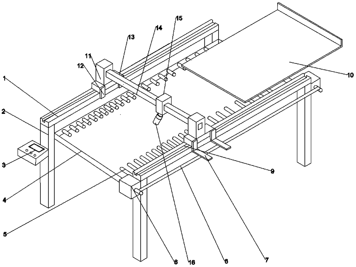
[0026] see Figure 1~5 , in an embodiment of the present invention, a steel plate cutting device that is convenient for precise positioning includes a slide rail 1, a support column 2 and a frame body 4, and support columns 2 are provided at the corners of the frame body 4, and the support column in the upper left corner 2. The surface is connected to the control panel 3. The inner surfaces of the left and right sides of the frame body 4 are rotated and connec...


PUM


Abstract

The invention discloses a steel plate cutting device convenient to position accurately. The steel plate cutting device convenient to position accurately comprises slide rails, support pillars and a frame body. The support pillars are arranged on corners of the frame body; a control panel is connected to the surface of the support pillar on the left upper corner; rolling shafts are rotatably connected to inner surfaces of the left side and the right side of the frame body; the slide rails are arranged above the left end and the right end of the frame body in parallel; the support pillars are connected to the end points of the slide rails; sliding chutes are formed in the surfaces of the slide rails; a support frame is connected above the rolling shafts; a steel plate to be processed is placed onto the support frame; and after determining the position to be processed through moving support plates a on two sides, the position of the steel plate is fixed through electrifying an electromagnet, the steel plate is moved to the position under a laser cutting head, a moving device can enable the laser cutting head to move left and right, a lifting table can enable the laser cutting head tomove up and down, and the moving device can enable the laser cutting head to move front and back. The steel plate cutting device is simple to operate and can work at multiple directions, so that the steel plate can be accurately positioned and cut.

Description

technical field [0001] The invention relates to the technical field of cutting, in particular to a steel plate cutting device convenient for precise positioning. Background technique [0002] The steel plate is a flat-shaped steel material that is poured with molten steel and pressed after cooling. There are flat and rectangular shapes, which can be directly rolled or cut from wide steel strips. [0003] Flame or laser cutting is often used for steel plate cutting, which uses the high temperature generated during the combustion of iron oxide to cut the steel plate placed on the cutting platform. Due to the high temperature of flame cutting, the cutting platform may be damaged, and the existing cutting device is large. Most of them cannot precisely position the steel plate, therefore, those skilled in the art provide a steel plate cutting device that is convenient for precise positioning, so as to solve the problems raised in the above-mentioned background technology. Conte...

Claims


Application Information

Patent Timeline
IPC IPC(8): B23K26/38B23K26/70
CPCB23K26/38B23K26/702
Inventor 薛立照
Owner 芜湖立普德机械科技有限公司
Why Eureka
Try Eureka