Manual cleaning device for writing brush cleaning

A cleaning device and cleaning technology, which is applied to devices for removing pen nibs, printing and writing utensils, etc., can solve the problem of soiling the user's fingers, etc., and achieve the effect of speeding up the drying speed and improving the drying speed.

Inactive Publication Date: 2018-10-26
嘉善县干窑小学
View PDF0 Cites 8 Cited by
  • Summary
  • Abstract
  • Description
  • Claims
  • Application Information

AI Technical Summary

Problems solved by technology

[0003] In the process of cleaning the brush, wash until the brush is lifted out of the water, squeeze the brush with your fingers, and the water that seeps out of the brush will not have too much ink. Dirty user's fingers

Method used


Image

  • Manual cleaning device for writing brush cleaning
  • Manual cleaning device for writing brush cleaning
  • Manual cleaning device for writing brush cleaning

Examples


Embodiment 1

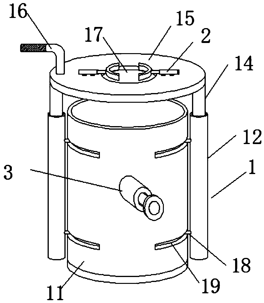
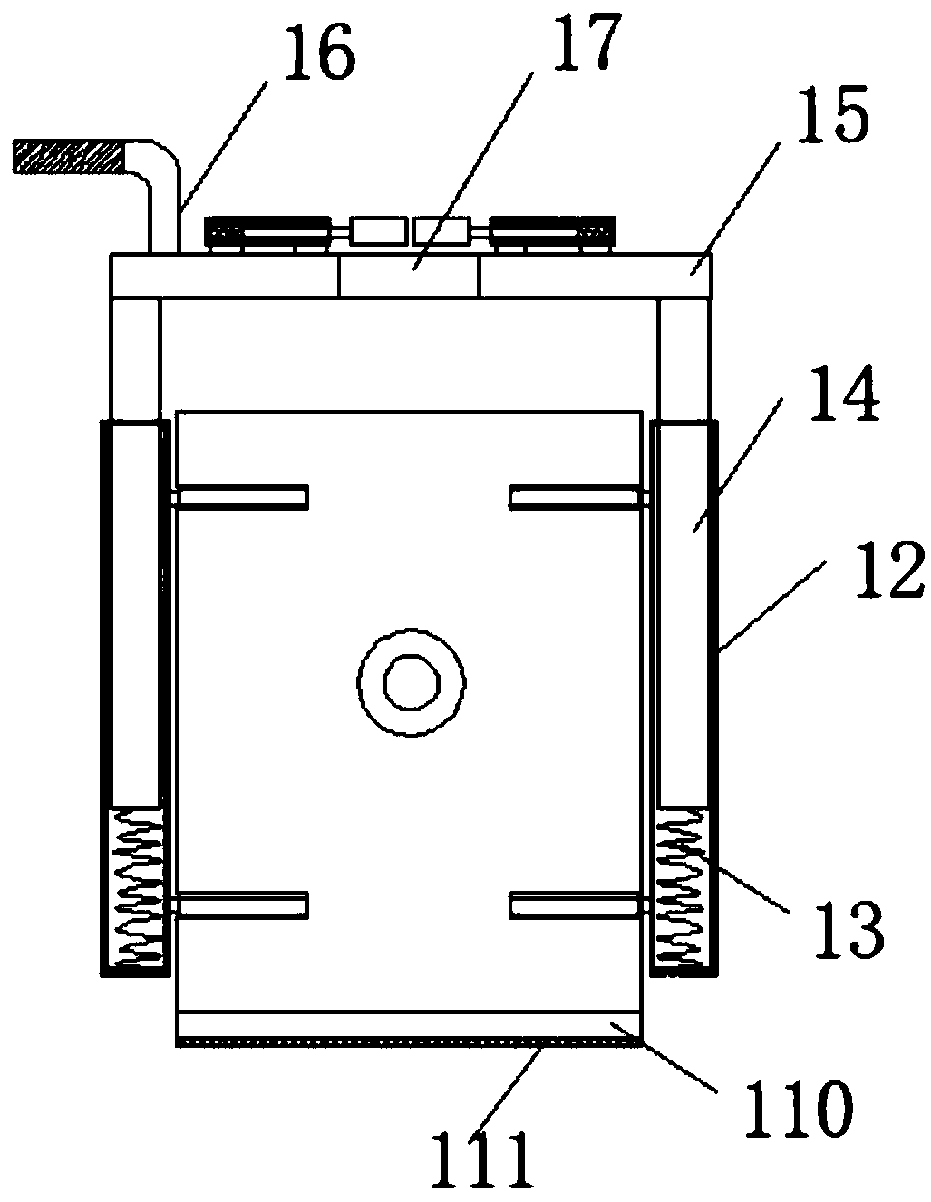
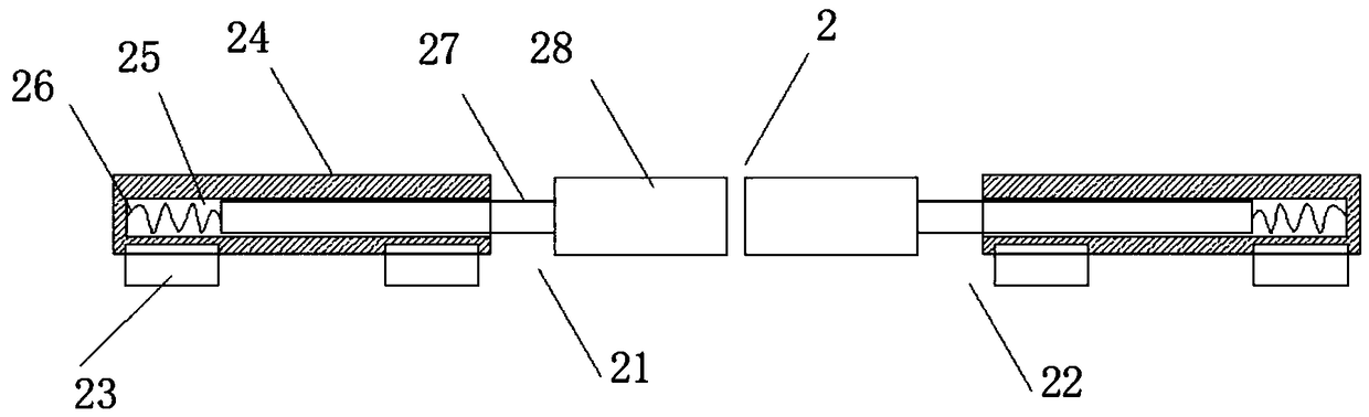
[0023] like figure 1 As shown, a kind of manual cleaning device that the present invention proposes is used for brush cleaning, comprises cleaning mechanism 1, the clamping mechanism 2 that is arranged on cleaning mechanism 1 top and the clamping mechanism 3 that is fixed on cleaning mechanism 1 both sides, and cleaning mechanism The function of 1 is to clean the brush, the function of the clamping mechanism 2 is to fix the brush, the function of the clamping mechanism 3 is to squeeze out the water absorbed on the tip of the brush, and the cleaning mechanism 1 includes a glass with cleaning liquid inside Cylinder 11, the outer walls of both sides of the glass cylinder 11 are provided with arc-shaped chute 19, the inside of chute 19 is engaged with slide rod 18, one end of slide rod 18 is engaged inside chute 19, and the other end of slide rod 18 is The sleeve 12 is welded, the first spring support 13 is arranged inside the sleeve 13, the bottom of the first spring support 13 i...

Embodiment 2

[0025] In addition, please continue to refer to Figure 2-5, different from the above embodiment, the chute 19 has an arc-shaped structure, the number of chute 19 is four, the left side wall of the glass cylinder 11 is provided with two chute 19, and the right side of the glass cylinder 11 is provided with two chute 19, and the two chutes 19 on the same side of the glass cylinder 11 are arranged in parallel, each chute 19 is engaged with a slide bar 18, and the slide bar 18 and the chute 19 slide, so that the chute 19 can be used The sliding rod 18 fixes the sleeve 12, and the sleeve 12 can be moved to slide back and forth on the chute 19. The handle 16 is vertically arranged on the top of the fixed table 15, and the left end of the handle 16 is wrapped with a sweat-absorbing belt, so that it can be absorbed by the sweat-absorbing belt. Sweat on the hands of the user improves the comfort of the user. A base 110 with a circular structure is provided at the bottom of the glass c...


PUM


Abstract

The invention discloses a manual cleaning device for writing brush cleaning and relates to the technical field of writing brush cleaning application. The manual cleaning device comprises a cleaning mechanism, a clamping mechanism, clamping and screwing mechanisms, a glass barrel body, a sleeve, a first spring bracket, a connecting rod, a fixed platform, a grip, a fixed hole, a sliding rod, a sliding chute, a base, an anti-slip mat, a first fixing clamp, a second fixing clamp, a fixed seat, a fixed barrel, a cavity, a second spring bracket, a telescopic rod, a clamping piece, a mounting barrel,a movable rod, a push handle, iron sheets, a through hole and a filter screen. The manual cleaning device has the beneficial effects that the clamping and screwing mechanisms are arranged on the front outer side wall and the rear outer side wall of the glass barrel body; therefore, when a writing brush is cleaned, the tip of the writing brush is lifted to the same height of the clamping and screwing mechanisms, cleaning fluid and ink adsorbed on the tip of the writing brush can be squeezed out through the iron sheets on the clamping and screwing mechanisms; according to the fact whether too much ink exists in the water seeped from the tip of the writing brush or not, whether the tip is cleaned or not can be judged; and water in the tip of the writing brush can be squeezed out by the clamping and screwing mechanisms.

Description

technical field [0001] The invention relates to the technical field of cleaning brushes, in particular to a manual cleaning device for cleaning brushes. Background technique [0002] The brush is a traditional writing tool that originated in China, and has gradually become a traditional painting tool. The brush was invented by the ancient Chinese people in the production practice. Drawing tools, although pencils, ballpoint pens, fountain pens, etc. are popular in the world today, writing brushes cannot be substituted. After the writing brush is used up, the nib of the writing brush needs to be cleaned to remove the ink on the nib. [0003] In the process of cleaning the brush, wash until the brush is lifted out of the water, squeeze the brush with your fingers, and the water that seeps out of the brush will not have too much ink. Dirty user's fingers. Therefore, it is necessary for us to improve such a manual cleaning device for brush cleaning, so as to overcome the above...

Claims


Application Information

Patent Timeline
Patent Type & Authority Applications(China)
IPC IPC(8): B43K13/02
CPCB43K13/02
Inventor 陈尔雨
Owner 嘉善县干窑小学
Why Eureka
Try Eureka