Full-automatic production line for LED lamp tube

A LED lamp tube, fully automatic technology, applied in the direction of auxiliary devices, lighting and heating equipment, coating, etc., can solve the problems of broken glass lamp tube, high labor cost, high error rate, etc., to speed up the drying speed and reduce the Labor cost, the effect of improving production efficiency

Active Publication Date: 2016-11-16
FOSHAN ELECTRICAL & LIGHTING
View PDF7 Cites 16 Cited by
  • Summary
  • Abstract
  • Description
  • Claims
  • Application Information

AI Technical Summary

Problems solved by technology

[0002] The production process of the LED lamp tube includes gluing the lamp bar, guide wires at both ends of the lamp tube, welding of the power supply, installation of the lamp cap, aging treatment of the lamp cap, and various detection parts, etc. Due to technical limitations, the existing technology generally adopts semi-manual Mechanized way to produce lamps, but now the labor cost is very high, and the error rate of manual operation is high, which affects the quality of the product, and the mix of manual and mechanized requires frequent manual handling, glass lamps are prone to breakage, which can be seen High cost, low production efficiency, low product qualification rate and other problems of the technical lamp tube production line

Method used


Image

  • Full-automatic production line for LED lamp tube
  • Full-automatic production line for LED lamp tube
  • Full-automatic production line for LED lamp tube

Examples


Embodiment Construction

[0046]In order to make the object, technical solution and advantages of the present invention clearer, the present invention will be further described in detail below in conjunction with the accompanying drawings. It is only stated here that the words for directions such as up, down, left, right, front, back, inside, and outside that appear or will appear in the text of the present invention are only based on the accompanying drawings of the present invention, and are not specific to the present invention. limited.

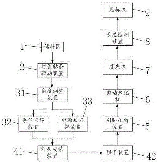
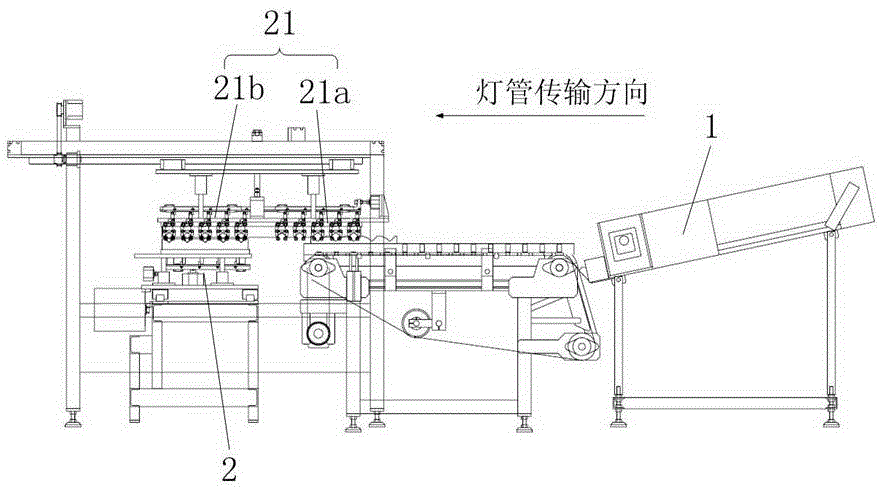
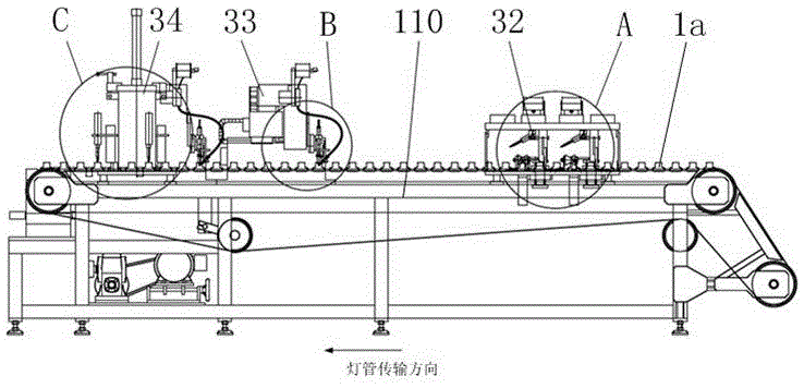
[0047] See attached figure 1 to attach Figure 22 , the present invention discloses a fully automatic production line for LED lamp tubes, which includes a conveyor chain 110 for conveying lamp tubes and a material storage area, a light bar spot glue tube area, a spot welding area, and a lamp cap installation area arranged sequentially along the conveyor chain 110 . Each part is described in detail below.

[0048] see figure 2 , the light bar dispensing tube a...


PUM


Abstract

The invention discloses a full-automatic production line for an LED lamp tube. The full-automatic production line comprises a conveying chain, a material storage area, a lamp strip dispensing tube sticking area, a spot welding area and a lamp head installation area, wherein the conveying chain is used for conveying the lamp tube, and the material storage area, the lamp strip dispensing tube sticking area, the spot welding area and the lamp head installation area are sequentially arranged along the conveying chain. The lamp strip dispensing tube sticking area comprises a lamp strip dispensing device used for conducting glue feeding on the upper surface of a lamp strip, a lamp tube adhesive tape driving device used for driving the lamp tube to move back and forth in the length direction of the lamp strip and a lamp tube feeding and discharging device. The lamp tube spot welding area comprises a first angle adjusting device, a guide wire spot welding device and a power board spot welding device. The first angle adjusting device drives the lamp tube entering the lamp tube spot welding area to rotate till the lamp strip is located at the bottom of the lamp tube. The lamp head installation area comprises a lamp head installation device and a drying device. The lamp head installation device comprises a transfer mechanical arm and a leading wire alignment mechanism. The drying device comprises a lamp tube feeding and discharging mechanism, a lamp tube rotating mechanism used for conveying the lamp tube and a lamp tube heating mechanism which is arranged on the lamp tube rotating mechanism and used for heating and curing a lamp head. The full-automatic production line for the LED lamp tube is high in efficiency.

Description

technical field [0001] The invention relates to the field of lamp tube production, in particular to an automatic production line for LED lamp tubes. Background technique [0002] The production process of the LED lamp tube includes gluing the lamp bar, the guide wire at both ends of the lamp tube, the welding of the power supply, the installation of the lamp cap, the aging treatment of the lamp cap, and various detection parts. Mechanized way to produce lamps, but now the labor cost is very high, and the error rate of manual operation is high, which affects the quality of the product, and the mixing of manual and mechanized requires frequent manual handling, and glass lamps are prone to breakage. The high-tech lamp tube production line has problems such as high cost, low production efficiency, and low product qualification rate. Contents of the invention [0003] The technical problem to be solved by the present invention is to provide a fully automatic production line fo...

Claims


Application Information

Patent Timeline
Patent Type & Authority Applications(China)
IPC IPC(8): B23K37/00B23P19/00F21K9/90B05C5/02B05C13/02
CPCB05C5/02B05C13/02B23K37/00B23P19/00F21K9/90
Inventor 叶正鸿许问津郭维国邓少广
Owner FOSHAN ELECTRICAL & LIGHTING
Why Eureka
Try Eureka