Automatic sand conveying system

An automatic, sand conveying pipe technology, applied to conveyors, transportation and packaging, mixers, etc., can solve problems such as low degree of automation, proppant clogging, and incomplete sand discharge

Pending Publication Date: 2019-11-22
SICHUAN HONGHUA PETROLEUM EQUIP
View PDF0 Cites 4 Cited by
  • Summary
  • Abstract
  • Description
  • Claims
  • Application Information

AI Technical Summary

Problems solved by technology

[0005] 1. In the prior art, hooks, broken bags, sand unloading and sorting of damaged packaging bags all need to be manually operated by operators, which has a low degree of automation and low efficiency;
[0006] 2. In the prior art, the crane needs to be dispatched temporarily during the bag breaking process, and many people are required to cooperate with the operation, which may easily lead to incomplete sand unloading and random flying of proppant during the hoisting process, resulting in waste of proppant. Increased operating costs;
[0007] 3. In the prior art, since the bag breaking device and sand storage device are non-modular designs, the bag breaking device, sand storage device, sand conveying device, sand storage device and various auxiliary equipment need to be transported separately and independently. It needs to be hoisted and installed separately after the site, so the transportation and installation costs in the transportation and installation process are relatively high;
[0008] 4. In the prior art, since the proppant is transported in a non-closed manner and exposed to the air, the proppant cannot be kept in a dry state in rainy and snowy weather, and it is easy to cause blockage of the proppant during sand transportation;
[0009] 5. In the prior art, since the proppant is exposed to the air, it is easy to cause air pollution during bag breaking and transportation, which does not meet the requirements of HSE

Method used


Image

  • Automatic sand conveying system
  • Automatic sand conveying system
  • Automatic sand conveying system

Examples


Embodiment 1

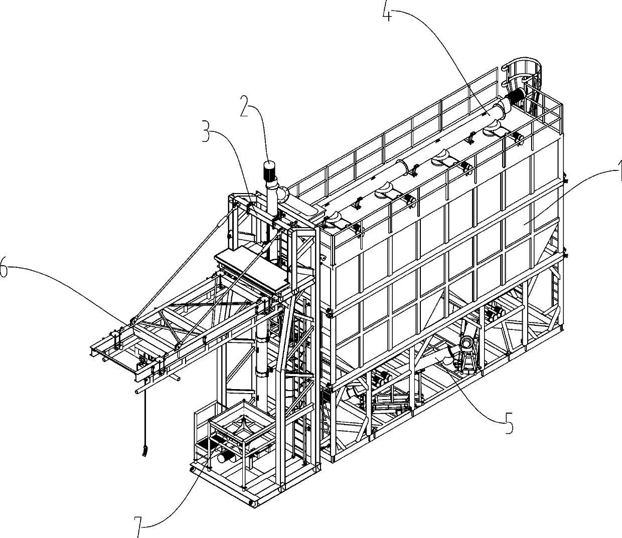
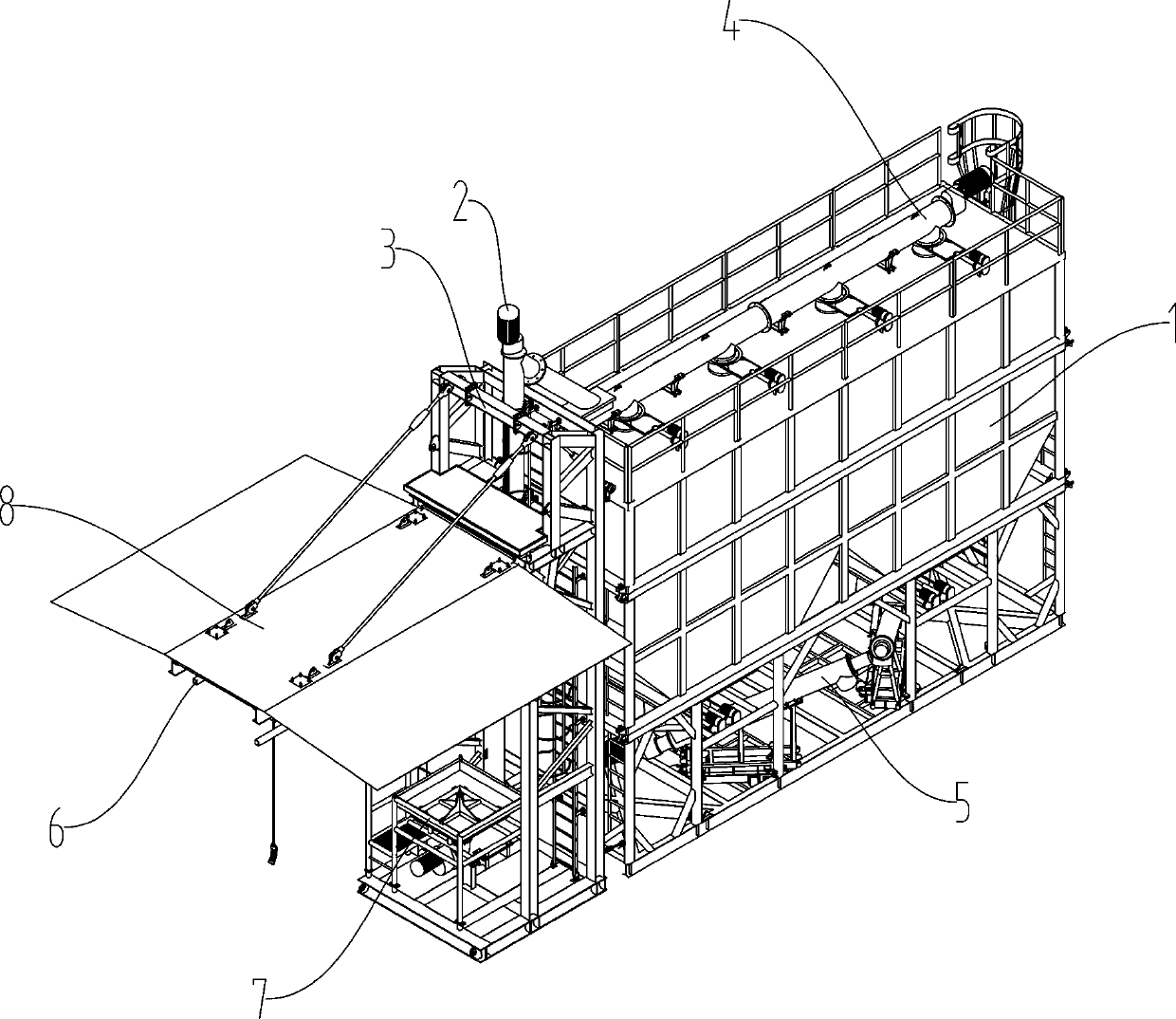
[0117] like figure 1 As shown, the automatic sand conveying system consists of sand storage device assembly 1, vertical spiral sand conveying assembly 2, mounting frame assembly 3, horizontal spiral sand conveying assembly 4, spiral sand discharging assembly 5, and sand bag lifting device 6 It is composed of the bag breaking device 7, the sand storage device assembly 1 is placed on a flat ground, the vertical screw sand conveying assembly 2 is fixedly connected with the mounting frame assembly 3, and the mounting frame assembly 3 is connected to the front end of the sand storage device assembly 1 Fixed connection, the horizontal screw sand conveying assembly 4 is fixedly connected to the top of the sand storage device assembly 1, the sand bag lifting device 6 is fixedly connected to the upper part of the mounting frame assembly 3, and the bag breaking device 7 is fixed to the bottom of the mounting frame assembly 3 connection, in other embodiments such as figure 2 As shown, ...

Embodiment 2

[0127] like figure 1 As shown, it is consistent with the description of Embodiment 1, and will not be repeated here.

[0128] like image 3 As shown, it is consistent with the description of Embodiment 1, and will not be repeated here.

[0129] like Figure 5 As shown, it is consistent with the description of Embodiment 1, and will not be repeated here.

[0130] like Image 6 As shown, the horizontal spiral sand conveying assembly 4 includes a horizontal spiral sand conveying pipe 41, a horizontal spiral sand conveying pipe outlet 43 set at the bottom of the horizontal spiral sand conveying pipe 41, and a horizontal spiral sand conveying pipe 41 at the top of one end of the horizontal spiral sand conveying pipe 41. The feed port 42 of the spiral sand conveying pipe, the bracket 46 that fixes the horizontal spiral sand conveying pipe 41 on the top of the sand storage device assembly 1, and the driving motor 44 of the horizontal spiral sand conveying pipe fixedly connected t...

Embodiment 3

[0137] like figure 1 As shown, it is consistent with the description of Embodiment 1, and will not be repeated here.

[0138] like image 3 As shown, it is consistent with the description of Embodiment 1, and will not be repeated here.

[0139] like Figure 5 As shown, it is consistent with the description of Embodiment 1, and will not be repeated here.

[0140] like Image 6 As shown, the horizontal spiral sand conveying assembly 4 includes a horizontal spiral sand conveying pipe 41, a horizontal spiral sand conveying pipe outlet 43 set at the bottom of the horizontal spiral sand conveying pipe 41, and a horizontal spiral sand conveying pipe 41 at the top of one end of the horizontal spiral sand conveying pipe 41. The feed port 42 of the spiral sand conveying pipe, the bracket 46 that fixes the horizontal spiral sand conveying pipe 41 on the top of the sand storage device assembly 1, and the driving motor 44 of the horizontal spiral sand conveying pipe fixedly connected t...


PUM


Abstract

The invention relates to the field of petroleum drilling and mining equipment, and particularly relates to an automatic sand conveying system for carrying out modular conveying and full-closed automatic sand conveying. The automatic sand conveying system involves a sand storage device assembly connected with a foundation, a vertical spiral sand conveying assembly fixedly connected with the sand storage device assembly, a mounting frame assembly used for fixing the vertical spiral sand conveying assembly, a horizontal spiral sand conveying assembly fixedly connected with the top of the sand storage device assembly, a spiral sand outlet assembly fixedly connected with the inner bottom of the sand storage device assembly, a sand bag lifting device fixedly connected with the upper part of themounting frame assembly, and a bag breaking device fixedly connected with the mounting frame assembly, and further comprises a rain shielding device fixedly connected with the sand bag lifting device.According to the automatic sand conveying system, the structure is adopted, so that the conveying modularization and the propping agent fully-closed conveying can be realized, and meanwhile, the automatic operation is carried out in the whole process.

Description

technical field [0001] The invention relates to the field of oil drilling and production equipment, in particular to an automatic sand conveying system capable of modularized transportation and fully enclosed automatic transportation of sand and gravel. Background technique [0002] Shale gas fracturing requires the use of a large amount of fracturing proppant. Domestic fracturing proppants are all in the form of bags. The sand unloading process usually uses a crane to lift the sand bag from the ground to the top of the sand tank nearly 10 meters above the ground. , assisted by the operator on the top of the sand tank to complete the operations of breaking the bag and unloading the sand, and then the crane hoisted the damaged packaging bag on the top of the tank or placed it on the ground with the assistance of the ground personnel, and then the ground operator re-hooked it , lift new sand bags, and complete the sand loading operation again and again. [0003] This kind of ...

Claims


Application Information

Patent Timeline
Patent Type & Authority Applications(China)
IPC IPC(8): B65G65/32B65G65/46B65G69/00B65B69/00B01F15/02
CPCB65G65/32B65G65/46B65G69/00B65B69/0008B65B69/0041B65G2201/045B01F35/71B01F35/71705B65B69/0091B65D88/32
Inventor 田雨于芳周珍珍李泓杉魏荣税淼
Owner SICHUAN HONGHUA PETROLEUM EQUIP
Why Eureka
Try Eureka