
Water supply device structure for improving overflow

A water replenisher and water replenishment technology, which is applied in water supply devices, flushing equipment with water tanks, buildings, etc., can solve the problems of poor overflow capacity of overflow pipes, and achieve the effects of stable water replenishment, convenient adjustment and reliable function.

Pending Publication Date: 2018-10-26
XIAMEN R&T PLUMBING TECH
View PDF0 Cites 0 Cited by
  • Summary
  • Abstract
  • Description
  • Claims
  • Application Information

AI Technical Summary

Problems solved by technology

Existing water replenishers usually include a water inlet and a water outlet. The water at the water outlet flows to the toilet through the overflow pipe to replenish water for the toilet water seal. The water inlet is generally connected to the water inlet of the water inlet valve through a water replenishment hose. If the water replenishment hose is pulled away from the water replenishment port of the water inlet valve, the water inlet of the water replenisher will inhale air, and the gas sucked by the water replenisher will flow into the overflow pipe, which will cause the overflow capacity of the overflow pipe to be relatively poor

Method used


Image

  • Water supply device structure for improving overflow
  • Water supply device structure for improving overflow
  • Water supply device structure for improving overflow

Examples


no. 1 example

[0043] The first embodiment (using the communication port to form the gas barrier structure)

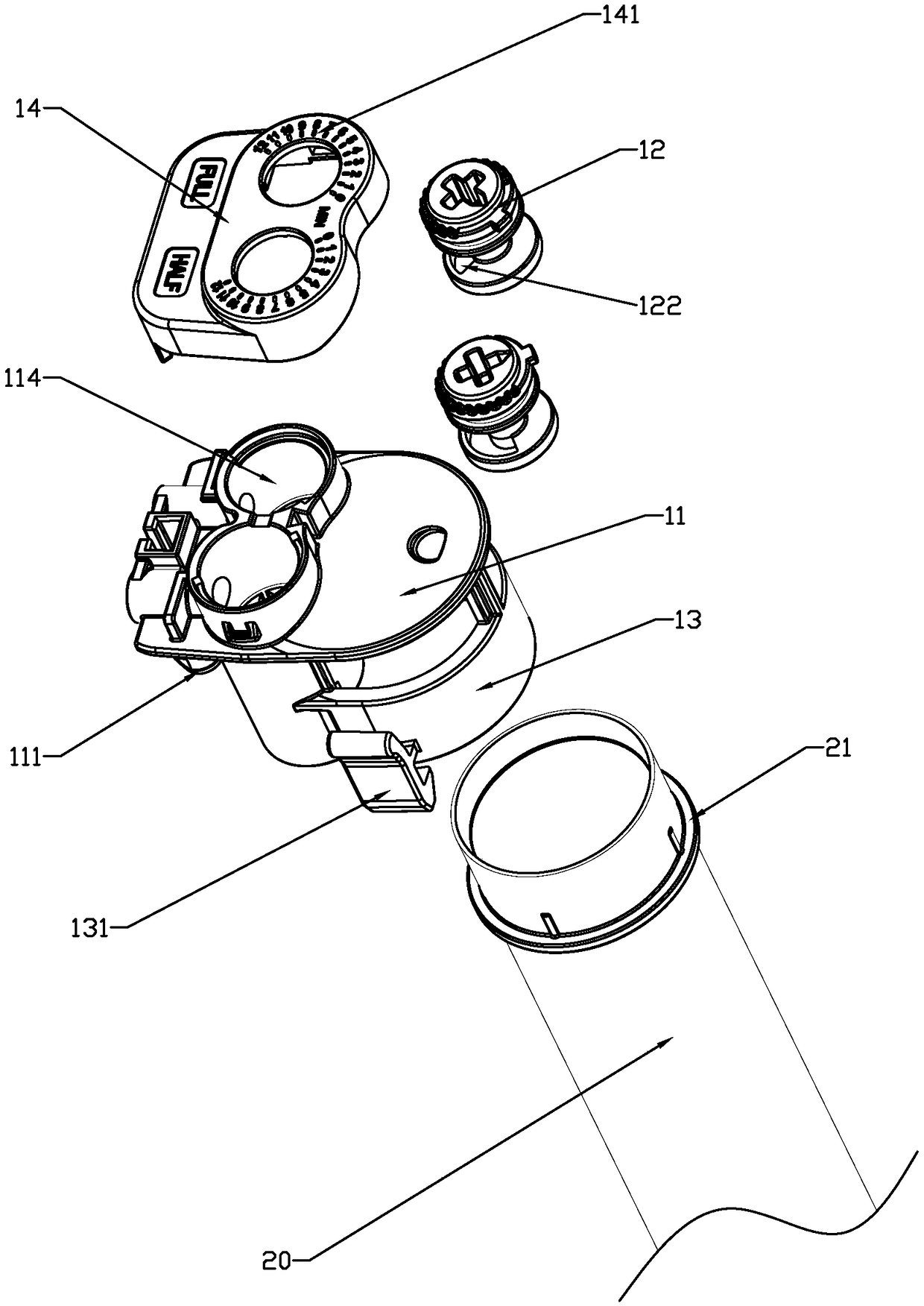
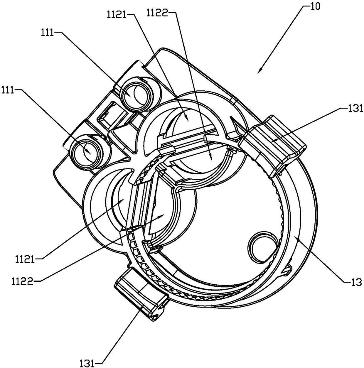
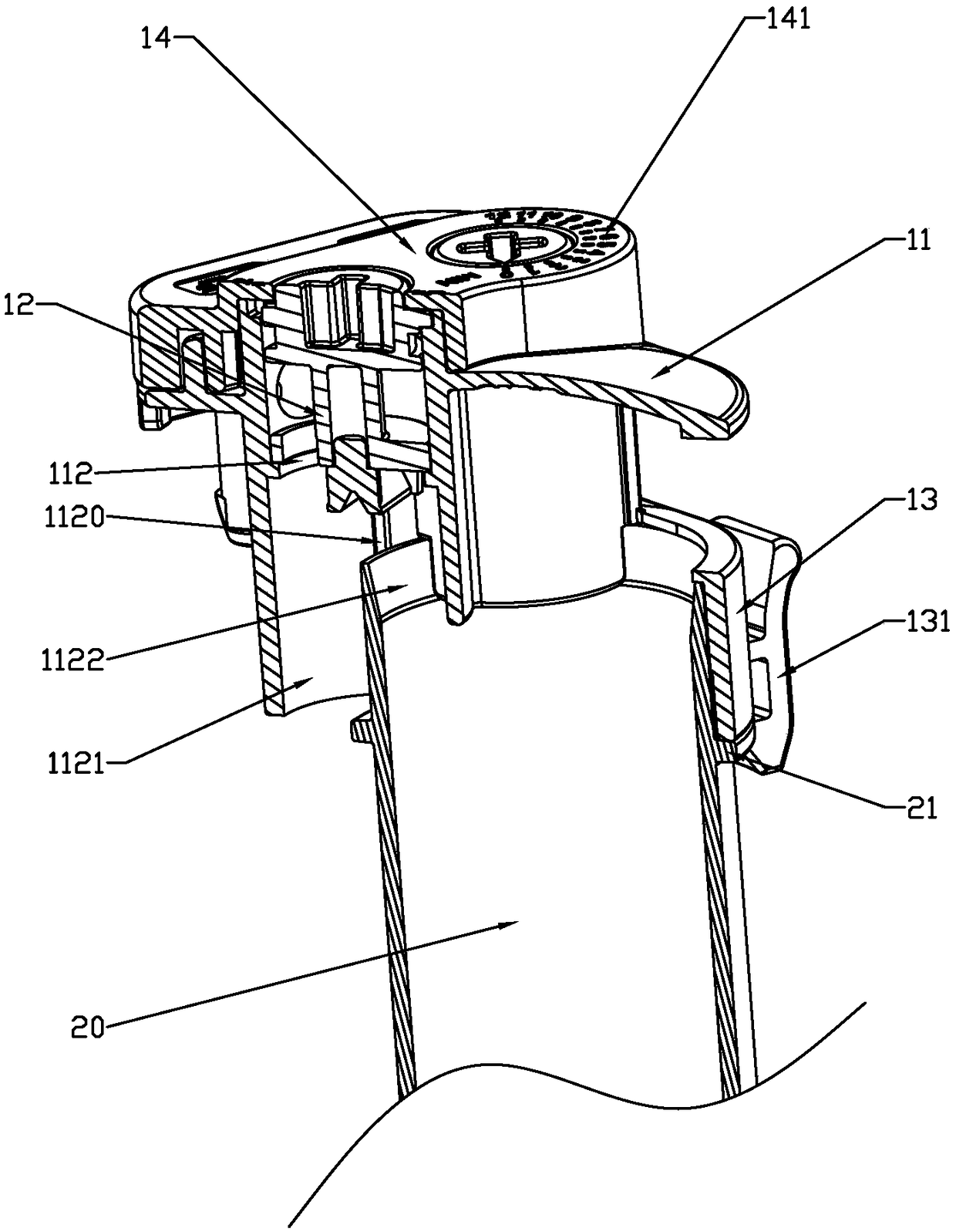
[0044] A water replenisher structure for improving overflow of the present invention includes a water replenishment body 11, the water replenishment body 11 is provided with a water inlet 111 and a water outlet 112, and the water inlet 111 is connected to a water replenishment inlet pipe (not shown), The water flow of the water outlet 112 is diverted to the overflow pipe 20 and outside the overflow pipe 20, and the overflow pipe 20 guides the water flow into the toilet water seal for water replenishment; and, the water replenishment body 11 is also provided with a water reducing The air barrier structure for the amount of air from the water supply body 11 when the overflow pipe 20 overflows, wherein the outside air from the water supply body 11 can enter the water supply body 11 through the water inlet 111 and / or the water outlet 112 middle.

[0045] Such as image 3 As shown, in t...

no. 2 example

[0052] Second Embodiment (Using a water inlet check valve to form a gas barrier structure)

[0053] Such as Figure 6 As shown, the main difference between this embodiment and the first embodiment is that in this embodiment, the gas blocking structure adopts a first one-way valve 1110 arranged on the water inlet 111, and the first one-way valve 1110 is in a normally closed state, and the first one-way valve 1110 is opened under the water pressure when the water inlet 111 is fed.

[0054] In this embodiment, the first one-way valve 1110 adopts a blocking ball. When overflowing, the blocking ball is in the lower position and blocks the water inlet 111, so that the airflow cannot enter the water outlet 112 from the water inlet 111, thereby reducing the influence of the airflow from the water supply body 11 on the overflow water and improving The overflow capacity of the overflow pipe 20.

no. 3 example

[0055] The third embodiment (a gas-blocking structure is formed by adopting longitudinal partitions and water outlet spacing)

[0056] Such as Figure 7 As shown, the main difference between this embodiment and the first embodiment is that: in this embodiment, the connecting sleeve 13 is fitted with the top of the overflow pipe 20, and the inner cavity of the connecting sleeve 13 is connected to the The inner cavity of the overflow pipe 20 is connected, and the connecting sleeve 13 is used as a part of the overflow pipe 20, that is, the top opening of the connecting sleeve 13 forms the overflow port of the overflow pipe 20, and the water in the water tank Flows from the top opening of the connecting sleeve 13 into the inner cavity of the connecting sleeve 13 , and then flows into the inner cavity of the overflow pipe 20 .

[0057] In this embodiment, the outlet of the replenishment water outlet channel 1122 is set in the overflow pipe 20, and the inner chamber of the replenis...


PUM


Abstract

The invention discloses a water supply device structure for improving overflow. The water supply device structure comprises a water supply body, the water supply body is provided with a water inlet and a water outlet, the water inlet is communicated with a water supply inlet pipe, water of the water outer flows to the inside and the outside an overflow pipe in a distributed manner and is led intoa toilet bowl water seal by the overflow pipe to supply water, matched water supply quantity is acquired by distributing supplied water without changing the water supply proportion of a water inlet valve supplying for the overflow pipe, the structure is simpler and more reliable, the influence of water pressure fluctuation of a water supply source on the water supply quantity is greatly reduced, so that the water supply quantity is more stable and more conveniently and reliably adjusted, the water supply body is further provided with an air blocking structure, the air blocking structure is used for reducing air amount from the water supply body when the overflow pipe overflows, and the air amount entering the overflow pipe can be further reduced, so that overflow effects are improved.

Description

technical field [0001] The invention relates to a water compensator structure for improving overflow. Background technique [0002] Most of the existing toilets will properly replenish water to the water seal through the water replenisher after flushing, so that the amount of water in the water seal is sufficient to prevent the odor in the sewage pipe from bursting out from the sewage outlet of the toilet and pollute the indoor air. Existing water replenishers usually include a water inlet and a water outlet. The water at the water outlet flows to the toilet through the overflow pipe to replenish water for the toilet water seal. The water inlet is generally connected to the water inlet of the water inlet valve through a water replenishment hose. If the water replenishment hose is pulled away from the water replenishment port of the water inlet valve, the water inlet of the water replenisher will inhale air, and the gas sucked in by the water replenisher will flow into the ov...

Claims


Application Information

Patent Timeline
Patent Type & Authority Applications(China)
IPC IPC(8): E03D1/32
CPCE03D1/32
Inventor 周洪文王志忠蓝晨龙王兴东
Owner XIAMEN R&T PLUMBING TECH
Learn More