
Water remover with overflow function

A water remover and functional technology, applied in the field of water remover with overflow function, can solve the problems of high production cost, damage to the surface of the liquid storage unit, and insufficient aesthetics, and achieve simple structure, good appearance, and overflow better effect

Pending Publication Date: 2019-03-15
JOMOO KITCHEN & BATHROOM
View PDF0 Cites 0 Cited by
  • Summary
  • Abstract
  • Description
  • Claims
  • Application Information

AI Technical Summary

Problems solved by technology

[0002] In sanitary products, the water remover is widely used, and it is usually installed at the bottom of the liquid storage unit (such as washbasin, sink, bathtub, etc.), and the water storage or drainage function of the liquid storage unit is realized by opening and closing the water remover ; The existing liquid holding unit is generally provided with an overflow hole, and the overflow function is realized through the overflow hole, but the opening of the overflow hole destroys the surface of the liquid holding unit, which seriously affects the integrity of the liquid holding unit, resulting in aesthetics Insufficient, and the overflow hole is easy to hide dirt and needs to be cleaned frequently; in addition, the liquid storage unit needs to be provided with a hollow interlayer for the overflow pipe to connect to the overflow hole through the hollow interlayer, so that the water in the overflow hole can flow from the overflow hole to the overflow hole. The overflow pipe is discharged. It should be noted that the existing overflow pipe has a pipe diameter requirement, which must meet the pipe diameter larger than 1.5-2CM set by the national standard, and then the distance between the hollow interlayers between the liquid storage units There are certain requirements, but the setting of the hollow interlayer makes the liquid storage unit must be set in double layers, which has a large volume and high production cost, and is not suitable for small volume or single-layer liquid storage units, so the existing water remover There is still room for further improvement

Method used


Image

  • Water remover with overflow function
  • Water remover with overflow function
  • Water remover with overflow function

Examples


Embodiment Construction

[0026] In order to make the technical problems, technical solutions and beneficial effects to be solved by the present invention clearer and clearer, the present invention will be further described in detail below in conjunction with the accompanying drawings and embodiments. It should be understood that the specific embodiments described here are only used to explain the present invention, not to limit the present invention.

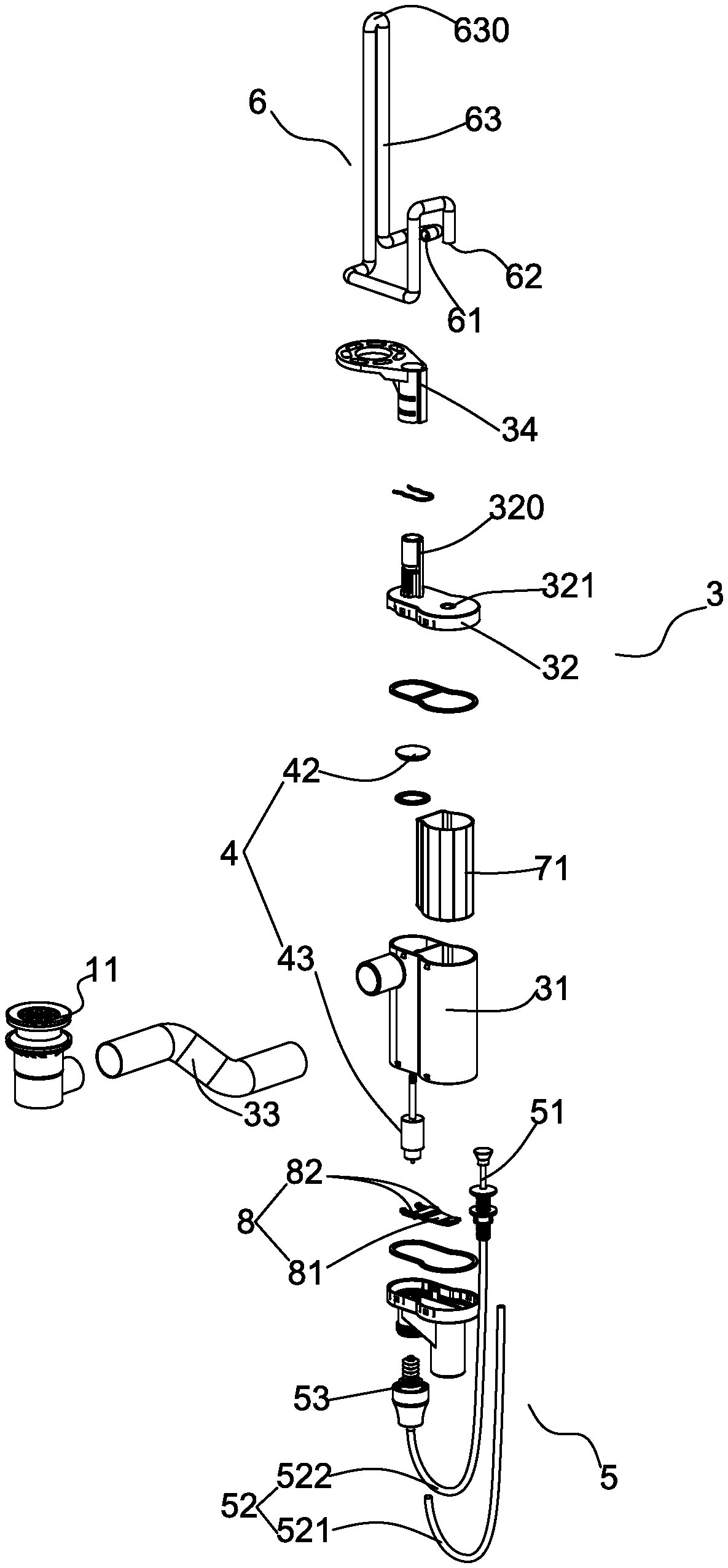
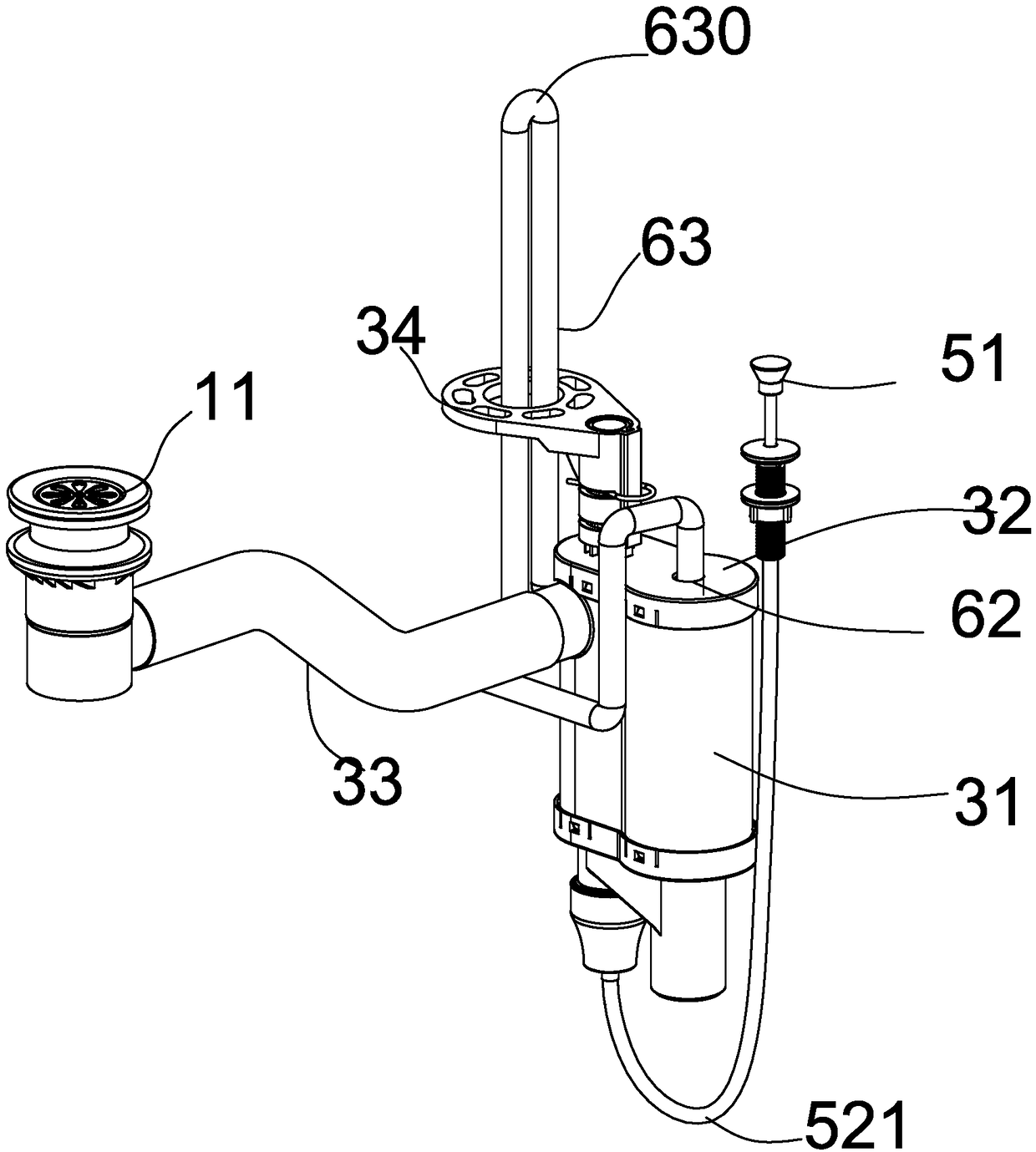
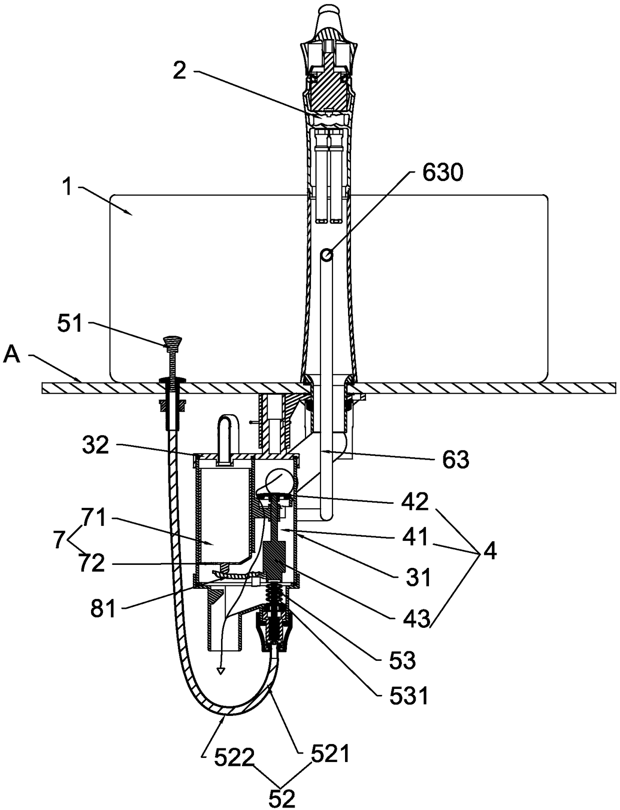
[0027] Such as Figure 1-3 As shown, the water remover with overflow function described in the present invention is used for the liquid holding unit 1 and the faucet 2; the liquid holding unit 1 can be bathroom products such as washbasins (basins), washing basins, bathtubs, etc. , the above-mentioned liquid holding unit 1 can be installed on the table A, and can also be installed below the table A; the faucet 2 is generally installed on the table A, and the water outlet is correspondingly arranged on the liquid holding unit 1; the present invention is b...


PUM


Abstract

The invention discloses a water remover with an overflow function. The water remover is used for a liquid receiving unit and a faucet; the water remover comprises a body, a water discharging assemblyand a control assembly; the body is mounted below the liquid receiving unit and guides a drain port of the liquid receiving unit; the water discharging assembly is mounted in the body and controls thewater through the control assembly; the water remover furthermore comprises an overflow pipe and a switch structure; the overflow pipe comprises a water inlet end, a water outlet end and a water passing section; the water inlet end is arranged on the body and located above the water discharging assembly; the water passing section is built in the faucet and is provided with an overflow surface; the water outlet end is communicated with the switch structure; the switch structure is connected with the water discharging assembly; the water pressure formed by the water flowing through the overflowsurface of the overflow pipe acts on the switch structure; and the switch structure is linked to drive the water discharging assembly to be opened or closed. The water remover is capable of solving the problem of destroying the wall integrity of the liquid receiving unit due to the opening of an overflow hole, and mounting the overflow pipe in the faucet.

Description

technical field [0001] The invention relates to the bathroom industry, in particular to a water drainer with an overflow function. Background technique [0002] In sanitary products, the water remover is widely used, and it is usually installed at the bottom of the liquid storage unit (such as washbasin, sink, bathtub, etc.), and the water storage or drainage function of the liquid storage unit is realized by opening and closing the water remover ; The existing liquid holding unit is generally provided with an overflow hole, and the overflow function is realized through the overflow hole, but the opening of the overflow hole destroys the surface of the liquid holding unit, which seriously affects the integrity of the liquid holding unit, resulting in aesthetics Insufficient, and the overflow hole is easy to hide dirt and needs to be cleaned frequently; in addition, the liquid storage unit needs to be provided with a hollow interlayer for the overflow pipe to connect to the o...

Claims


Application Information

Patent Timeline
Patent Type & Authority Applications(China)
IPC IPC(8): E03C1/22E03C1/23E03C1/232
CPCE03C1/22E03C1/23E03C1/2306E03C1/232
Inventor 林孝发林孝山郑继隆梁绍团高建祥
Owner JOMOO KITCHEN & BATHROOM
Learn More