Overflow valve system for railway locomotive

A railway locomotive and overflow valve technology, which is applied in the field of overflow valve system, can solve problems such as deformation of duckbill valve, and achieve the effects of reducing air pressure cross-flow, preventing water backflow, and preventing sewage and odor from being sprayed back.

Pending Publication Date: 2018-09-04
CHANGZHOU JIANHU JINCHENG VEHICLE EQUIP CO LTD
View PDF0 Cites 0 Cited by
  • Summary
  • Abstract
  • Description
  • Claims
  • Application Information

AI Technical Summary

Problems solved by technology

[0003] In order to solve the problem in the prior art that the duckbill valve will be deformed by the pressure difference, the present invention provides an overflow valve system used in railway locomotives that can effectively prevent the pressure difference between the inside and outside of the pipeline and discharge sewage smoothly.

Method used


Image

  • Overflow valve system for railway locomotive
  • Overflow valve system for railway locomotive
  • Overflow valve system for railway locomotive

Examples


Embodiment 1

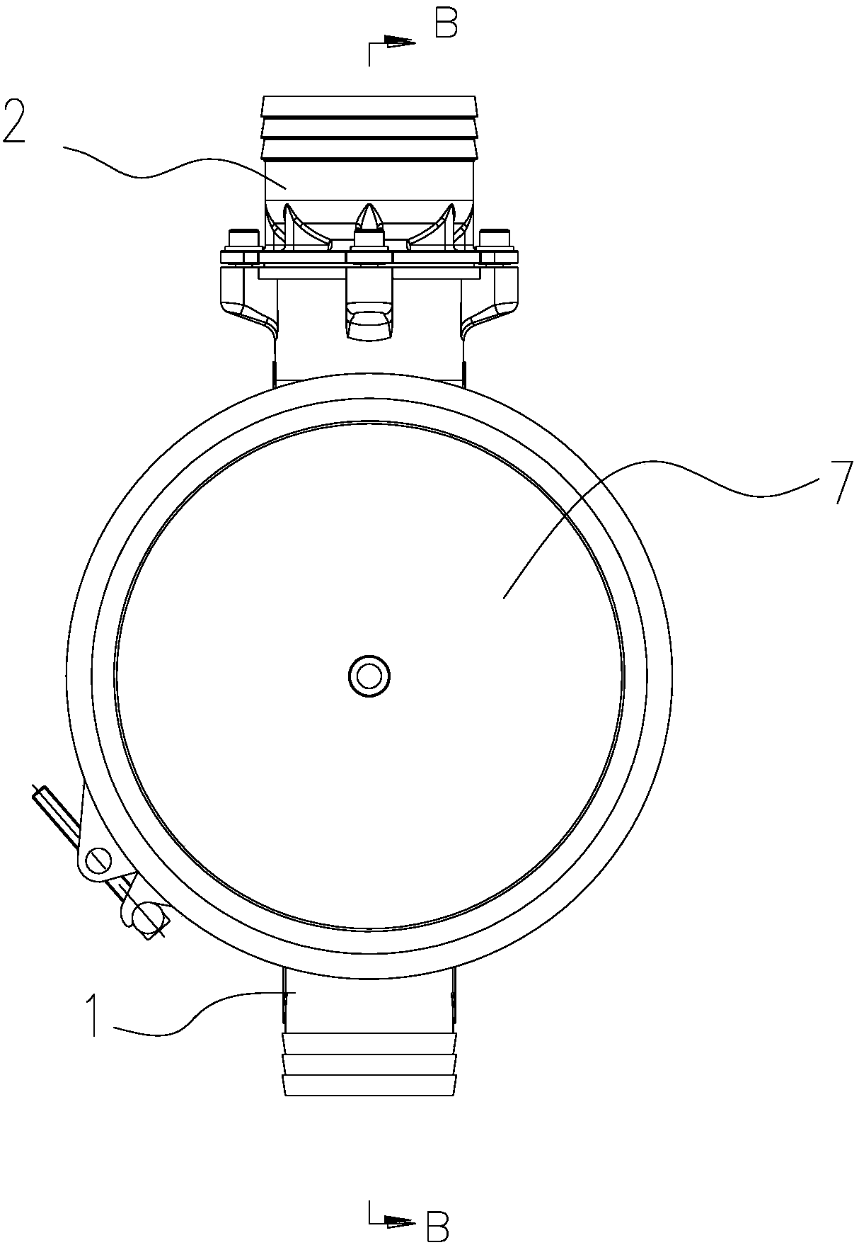
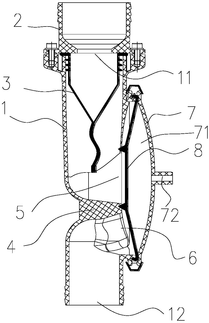
[0031] Such as Figure 1-2 , The pipe 1 is a straight pipe, and the second overflow valve body 7 is located on one side of the straight pipe.

Embodiment 2

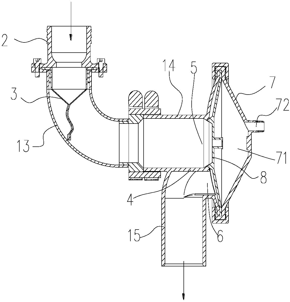
[0033] Such as image 3 , The pipeline 1 is an elbow, and the elbow includes an inlet elbow 13, a horizontal pipe 14 and a vertical pipe 15 in sequence along the water flow direction. The second overflow valve body 7 is located at the end of the horizontal pipe 14, and the water outlet 12 of the horizontal pipe 14 It is the first opening 5, the bottom end side wall of the horizontal tube 14 is a stop 4, and the second opening 6 is opened on the side wall of the vertical tube 15.

[0034] Specifically, the use of the relief valve system of the present invention in a locomotive has the following embodiments:


PUM


Abstract

The invention relates to the technical field of valves, in particular to an overflow valve system for a railway locomotive. The overflow valve system comprises a pipe allowing the water flow to pass through. The pipe comprises a water inlet and a water outlet, the water inlet is fixedly provided with a first overflow valve body, and a self-closed-type duckbill valve core is fixedly arranged between the first overflow valve body and the side wall of the water inlet. The pipe is internally provided with a blocking block, the portion, located in front of the blocking block, of the pipe side wallis provided with a first opening, the portion, located behind the blocking block, of the pipe side wall is provided with a second opening, the pipe is externally and fixedly provided with a second overflow valve body, and the second overflow valve body is internally provided with a valve cavity for enabling the first opening to communicate with the second opening. The valve cavity is internally provided with a rubber diaphragm, the rubber diaphragm isolates the first opening from the valve cavity and isolates the second opening from the valve cavity, and the side wall of the end, away from therubber diaphragm, of the second overflow valve body is provided with an air-through hole for enabling the valve cavity to communicate with the atmosphere. The pressure difference generated inside andoutside a box body is prevented, dirt discharging is smoother, and deodorization and anti-backwater effects are good.

Description

Technical field [0001] The invention relates to the technical field of valves, in particular to an overflow valve system used in railway locomotives. Background technique [0002] Rubber duckbill valves are often used in the prior art to effectively prevent liquid backflow. At present, because duckbill valves are made of flexible materials, there is a risk of deformation under the action of gas pressure difference during use, and thus cannot prevent liquid backflow. Effect. Summary of the invention [0003] In order to solve the problem of the duckbill valve deforming due to the pressure difference in the prior art, the present invention provides an overflow valve system for railway locomotives that can effectively prevent the pressure difference between the inside and outside of the pipeline and discharge sewage smoothly. [0004] The technical solutions adopted by the present invention to solve its technical problems are: [0005] An overflow valve system used in a railway locomot...

Claims


Application Information

Patent Timeline
Patent Type & Authority Applications(China)
IPC IPC(8): F16K15/14F16K15/18F16K7/17
CPCF16K15/148F16K7/17F16K15/18
Inventor 彭昭麟欧阳元陈强戚骐
Owner CHANGZHOU JIANHU JINCHENG VEHICLE EQUIP CO LTD
Why Eureka
Try Eureka