Coaxial linear motion and rotary motion converter
A technology of linear motion and rotary motion, applied in the field of transmission, can solve the problems of loose structure, misalignment of two transmission end axes, large volume, etc., and achieve the effect of compact structure, small volume and wide application range
- Summary
- Abstract
- Description
- Claims
- Application Information
AI Technical Summary
Problems solved by technology
Method used
Image

Examples
Embodiment Construction
[0024] The following will clearly and completely describe the technical solutions in the embodiments of the present invention with reference to the accompanying drawings in the embodiments of the present invention. Obviously, the described embodiments are only some, not all, embodiments of the present invention.
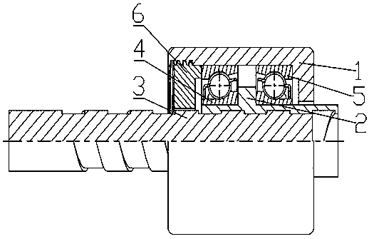
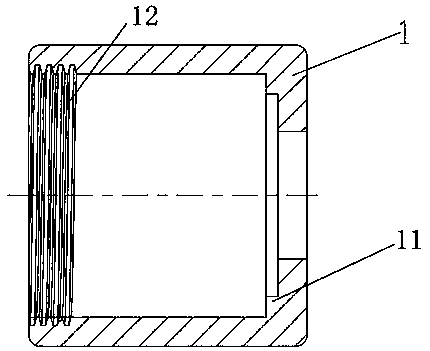
[0025] refer to Figure 1-6 , a coaxial linear motion and rotary motion converter, including a housing 1, a rotating nut 2, a linear guide rod 3, a first bearing 4, a second bearing 5 and an end cover 6, wherein the housing 1 It is arranged as a hollow cylindrical structure, one end of which is open and provided with a first bearing rib 11 , and the other end is open and provided with an internal thread 12 .
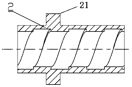
[0026] The rotating nut 2 is arranged in the housing 1 and one end thereof protrudes from the housing 1, and the protruding rotating thread 2 is connected to the rotating end, the outer periphery of the rotating nut 2 is provided with an annular protrusion 21, ...
PUM
 Abstract
Description
Claims
Application Information
 - R&D
- Intellectual Property
- Life Sciences
- Materials
- Tech Scout
- Unparalleled Data Quality
- Higher Quality Content
- 60% Fewer Hallucinations
Browse by: Latest US Patents, China's latest patents, Technical Efficacy Thesaurus, Application Domain, Technology Topic, Popular Technical Reports.
© 2025 PatSnap. All rights reserved.Legal|Privacy policy|Modern Slavery Act Transparency Statement|Sitemap|About US| Contact US: help@patsnap.com