
Access gate arrangement

A technology of door device and passage door, which is applied in the direction of inspection devices, roads, tracks, etc., can solve problems such as the difficulty of finding the best solution, and achieve the effects of money and space saving, effective use, and time saving

Active Publication Date: 2018-10-26
KONE CORP
View PDF13 Cites 2 Cited by
  • Summary
  • Abstract
  • Description
  • Claims
  • Application Information

AI Technical Summary

Problems solved by technology

[0005] The aforementioned flow control is in constant need of improvement, as optimal solutions are difficult to discover

Method used


Image

  • Access gate arrangement
  • Access gate arrangement
  • Access gate arrangement

Examples


Embodiment Construction

[0021] Reference will now be made in detail to embodiments, examples of which are illustrated in the accompanying drawings.

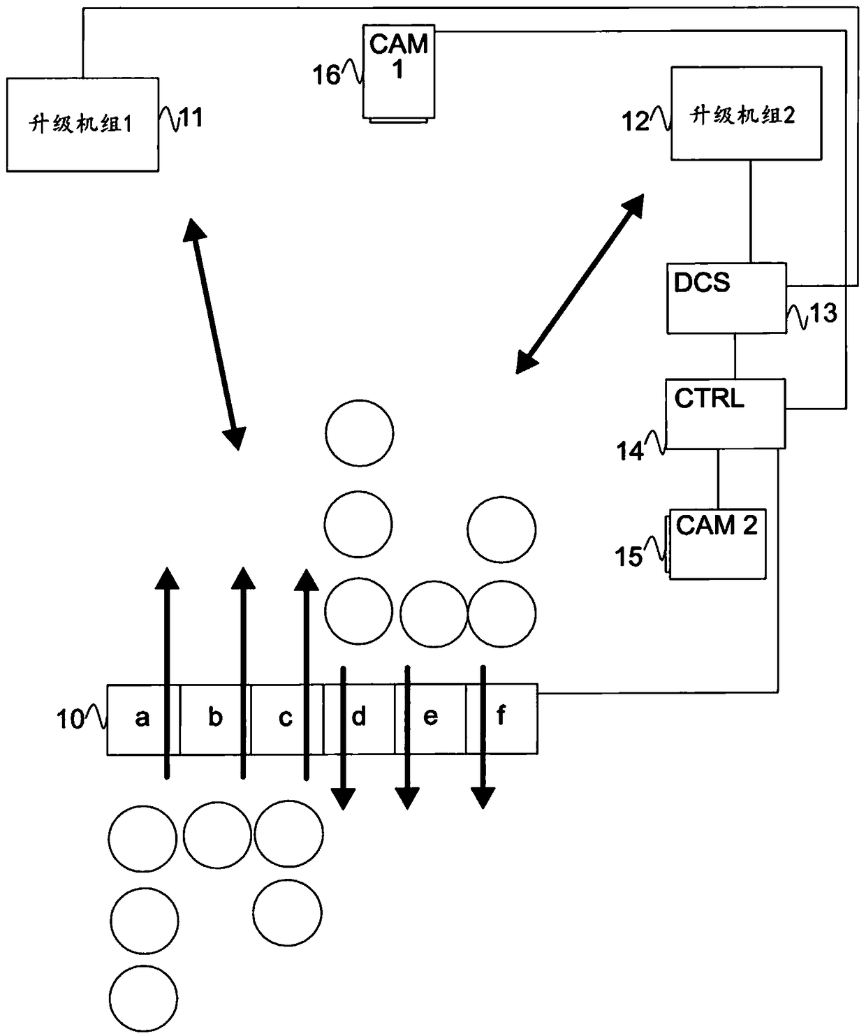
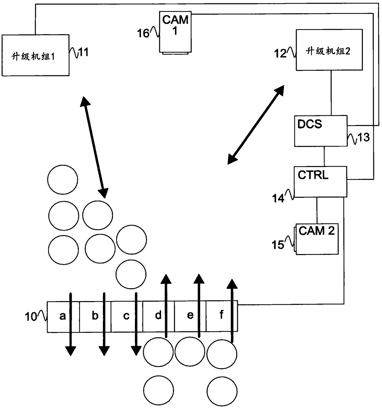
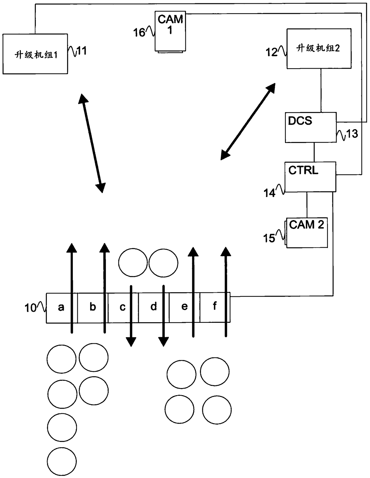
[0022] exist figure 1 In , a block diagram of an access door device is disclosed. The access door arrangement 10 includes six access doors 10a-10f. The individual doors 10a-10f can be controlled in such a way that they are configured in a one-way mode. exist figure 1 Among them, doors 10a-10c allow people to enter, and doors 10d-10f allow people to go out. This is an example of a neutral configuration and can be applied where either of the preferred directions is not required. The direction of the door can be changed, as described below.

[0023] The access door arrangement 10 is arranged to prevent unauthorized access to the lift groups 11 and 12, as shown in the figures. Lift sets are available in different configurations and sizes. The lift group is connected to a destination control system 13 . Obviously, the elevators can also be connected ...


PUM


Abstract

Managing passenger flows is an important issue in modern buildings. Particularly in high buildings, there will be a lot of people arriving and leaving typically through one access floor. When passenger flows are not managed and passengers are not instructed facilities of buildings are not in optimal use. People may be queueing for one elevator group when another elevator group is not used in fullcapacity. This can be improved by using an access gate arrangement where the controller of the access gate arrangement receives information from external systems in the building.

Description

Background technique [0001] Controlling the flow of people and traffic is important, but there are challenges to be solved. Typically, solutions are used in locations where large amounts of traffic are expected in order to control the movement of people or vehicles. [0002] One solution for indoor use is the destination control system for lifts. When a person arrives at the elevator lobby, he or she indicates the destination floor to the destination control system. The destination control system then assigns elevator runs and directs personnel to the correct elevator. Thus, the destination control system is able to gather people so that the elevator system is used as efficiently as possible. Furthermore, the destination control system knows or at least has a good assessment of the number of people traveling in the building. [0003] More often, for example, lifts are driven taking statistics, time and calendar into account. For example, in an office building, typically e...

Claims


Application Information

Patent Timeline
Patent Type & Authority Applications(China)
IPC IPC(8): G07C9/00B61B1/00B66B25/00B66B1/00
CPCG07C9/00G07C2011/04G07C9/38B61L27/40G05B15/02
Inventor J.琼斯K.伯格曼
Owner KONE CORP
Learn More