
Patsnap Eureka
For R&D, Patsnap Eureka makes reading and utilizing patents & technical documents easy.
Patsnap Eureka AIR
Designed for self-driven R&D workflows. Generate viable solutions, solve complex R&D challenges, empower your innovation with AI.

Patsnap Eureka Materials
Designed for material experts only. Revolutionize your material R&D, from search, analyze, to developing new materials.

TechResearch
Generate reliable direction feasibility study reports for your R&D in just a few steps.

TechSeek
Discover and master advanced knowledge NOW. Basics, ideas, possibilities, all at once.

TechMind
As an expert in R&D Theories, TechMind can generates customized viable solutions instantly.

TechRisk
Analyze your overall solution with one click, know your potential R&D risks in advance.

TechMonitor
Get weekly tech updates, stay abreast of the latest tech innovations and key insights.
Camera-shooting flashlight
A flashlight and barrel technology, applied in the field of camera flashlights, can solve the problems of inconvenient use of flashlights, blurred videos or photos, and achieve the effect of improving execution efficiency and acquisition efficiency.
- Summary
- Abstract
- Description
- Claims
- Application Information
AI Technical Summary
Problems solved by technology
Method used
Image

Examples
Embodiment 1
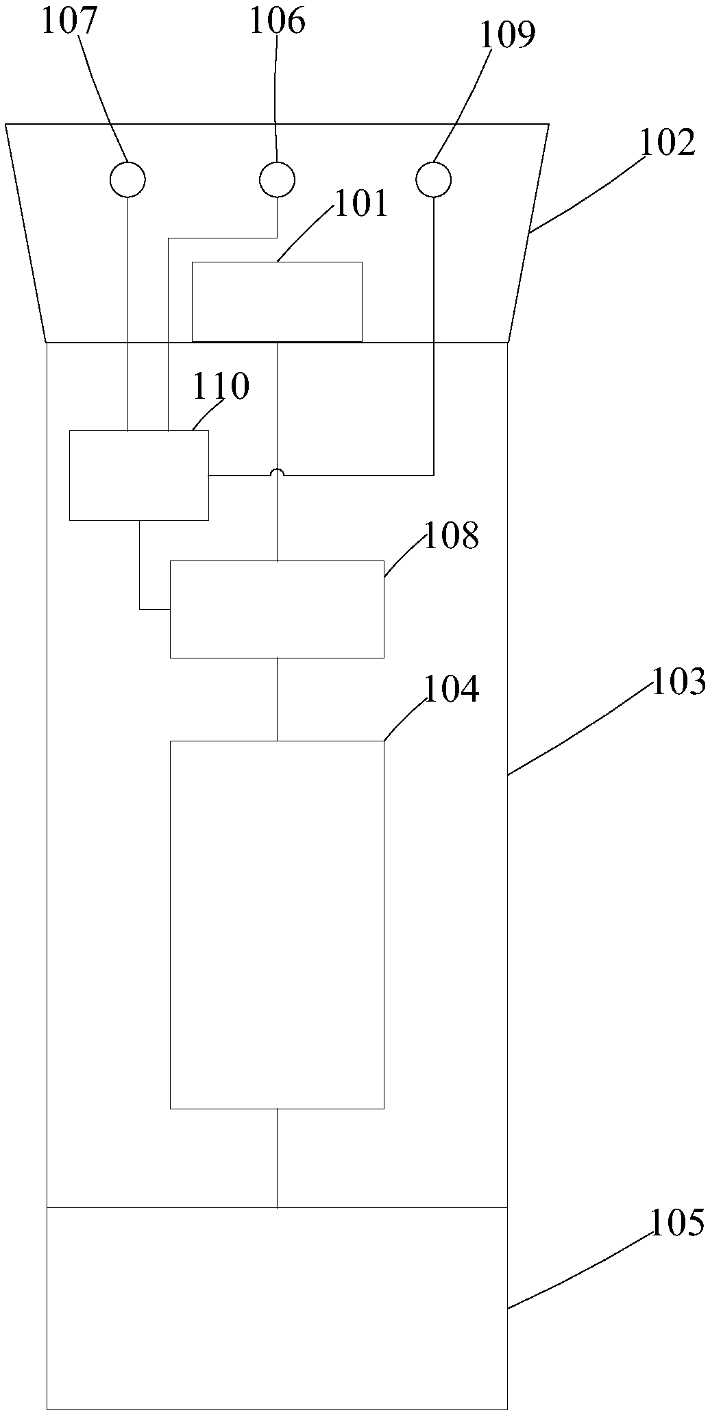
[0027] figure 1 A schematic structural diagram of the camera flashlight provided by Embodiment 1 of the present invention is shown in .
[0028] Such as figure 1 As shown, in this embodiment, the camera flashlight includes: lamp head 101, lampshade 102, barrel 103, battery compartment 104, charging tailstock 105, image acquisition unit 106, distance measuring sensor 107, current adjustment unit 108, illumination sensor 109 and controller 110.
[0029] The lampshade 102, the cylinder body 103 and the charging tailstock 105 are sequentially connected, the lamp head 101 is arranged in the lampshade 102, the battery compartment 104, the current regulating unit 108 and the controller 110 It is arranged inside the barrel 103, the image acquisition unit 106, the distance measuring sensor 107 and the illumination sensor 109 are arranged outside the lampshade 102, the lamp head 101 is connected to the current adjustment unit 108, the The current adjustment unit 108 is connected to t...
Embodiment 2
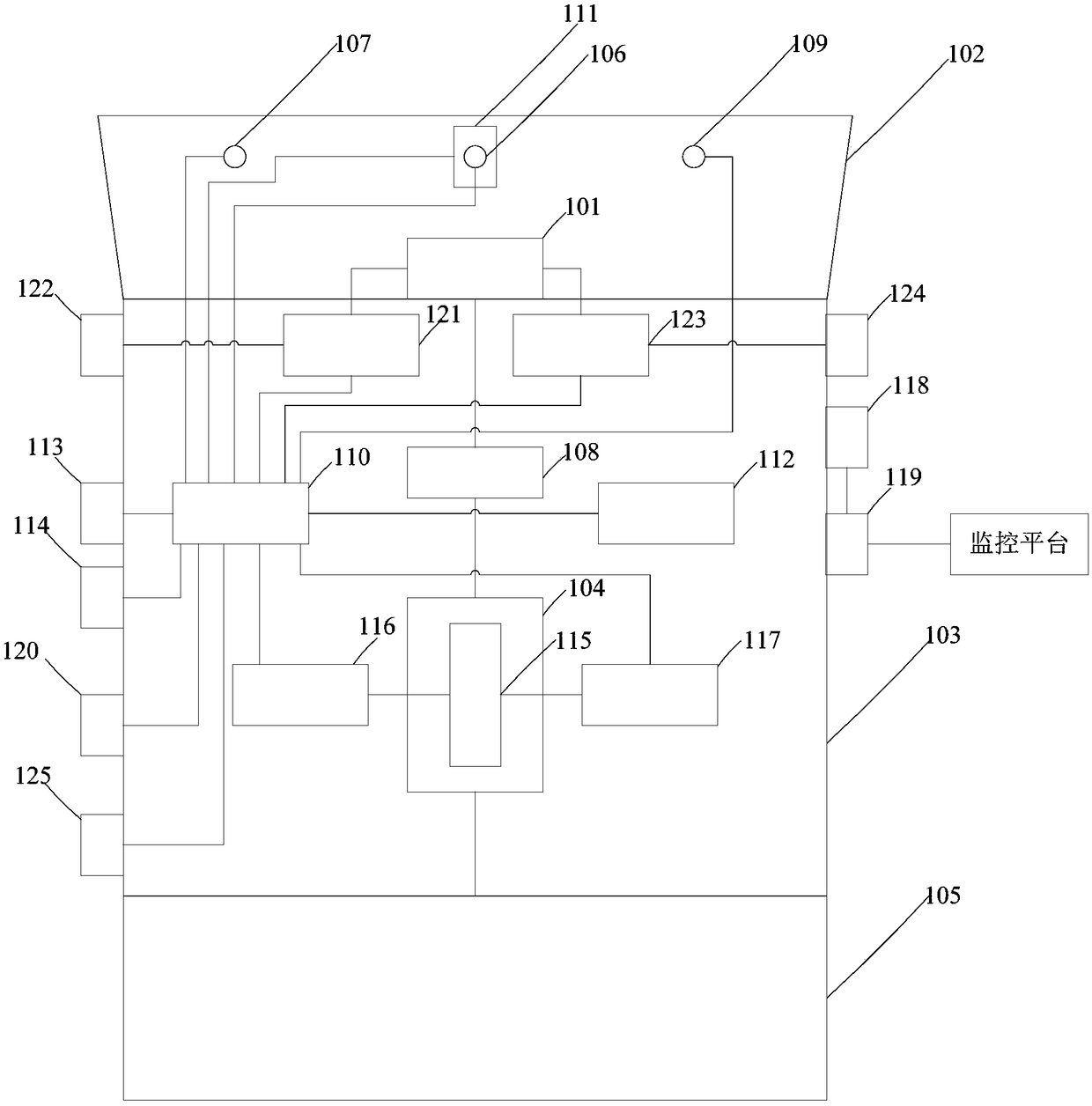
[0055] In order to better understand the above-mentioned device, an application example of the camera flashlight of the present invention will be described in detail below.
[0056] Such as figure 2 As shown, in this embodiment, the camera flashlight may include: a lamp head 101, a lampshade 102, a barrel 103, a battery compartment 104, a charging tailstock 105, an image acquisition unit 106, a distance measuring sensor 107, a current adjustment unit 108, and an illumination sensor 109. Controller 110, rotation unit 111, storage unit 112, proximity sensing unit 113, alarm unit 114, rechargeable battery 115, power management unit 116, fast charging unit 117, positioning unit 118, communication unit 119, display unit 120, A spotlight adjustment unit 121 , a spotlight button 122 , a floodlight adjustment unit 123 , a floodlight button 124 and a USB interface 125 .
[0057] Here, the lamp head 101 can adopt three high-brightness white LED lamp beads, the shape of the barrel 103 ...
PUM
 Abstract
Description
Claims
Application Information
 - R&D Engineer
- R&D Manager
- IP Professional
- Industry Leading Data Capabilities
- Powerful AI technology
- Patent DNA Extraction
Browse by: Latest US Patents, China's latest patents, Technical Efficacy Thesaurus, Application Domain, Technology Topic, Popular Technical Reports.
© 2024 PatSnap. All rights reserved.Legal|Privacy policy|Modern Slavery Act Transparency Statement|Sitemap|About US| Contact US: help@patsnap.com