Medical ear washing device

A technology for flushing device and medical use, which is applied to bathing devices, other medical equipment, enema/irrigator, etc., can solve the problems of poor practicability, inability to adjust the speed of the flushing tube, etc., and achieve the effect of enhanced practicability and convenient use.

Inactive Publication Date: 2018-11-02
王回芳
View PDF0 Cites 0 Cited by
  • Summary
  • Abstract
  • Description
  • Claims
  • Application Information

AI Technical Summary

Problems solved by technology

[0002] Existing medical ear irrigation devices on the market generally include a container for holding physiological saline, a hose connected to the inner cavity of the container is fixed at the bottom of the container, and an irrigation tube is fixed at the end of the hose. This medical ear irrigation device The structure is simple, but the speed of the water jetting out of the flushing pipe cannot be adjusted, and the practicability is poor

Method used


Image

  • Medical ear washing device
  • Medical ear washing device
  • Medical ear washing device

Examples


Embodiment Construction

[0017] The specific implementation manners of the present invention will be further described below in conjunction with the accompanying drawings, so as to make the technical solutions of the present invention easier to understand and grasp.

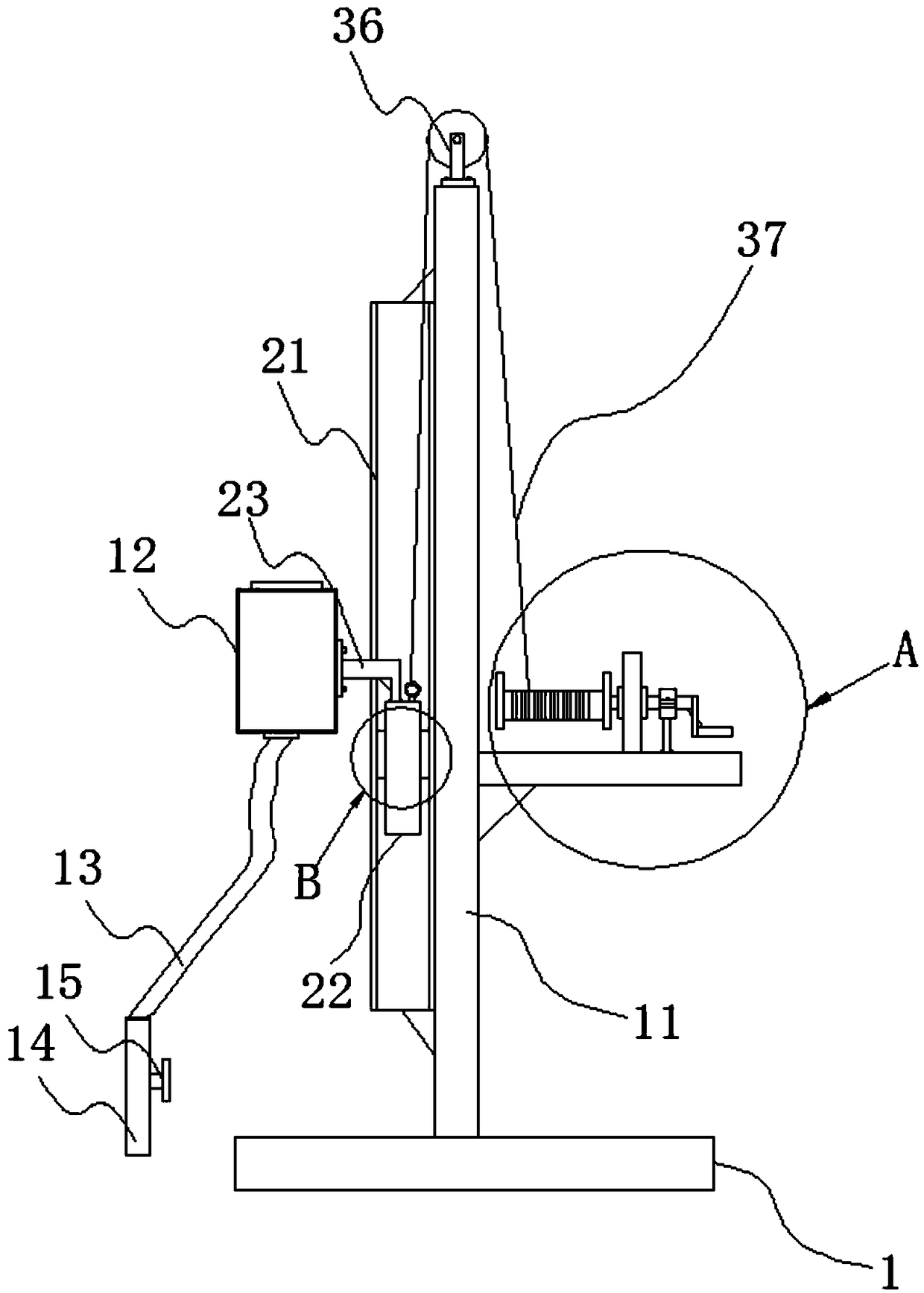
[0018] Such as figure 1 , 2 , 3, 4, 5, 6, and 7, a medical ear irrigation device includes a base 1, a support plate 11 welded on the top of the base 1, a container 12 for holding physiological saline, and the bottom of the container 12 is fixed There is a flexible pipe 13 communicating with the inner cavity of the container 12, a flushing pipe 14 is fixed at the end of the flexible pipe 13, and a control valve 15 is installed on the outer wall of the flushing pipe 14.

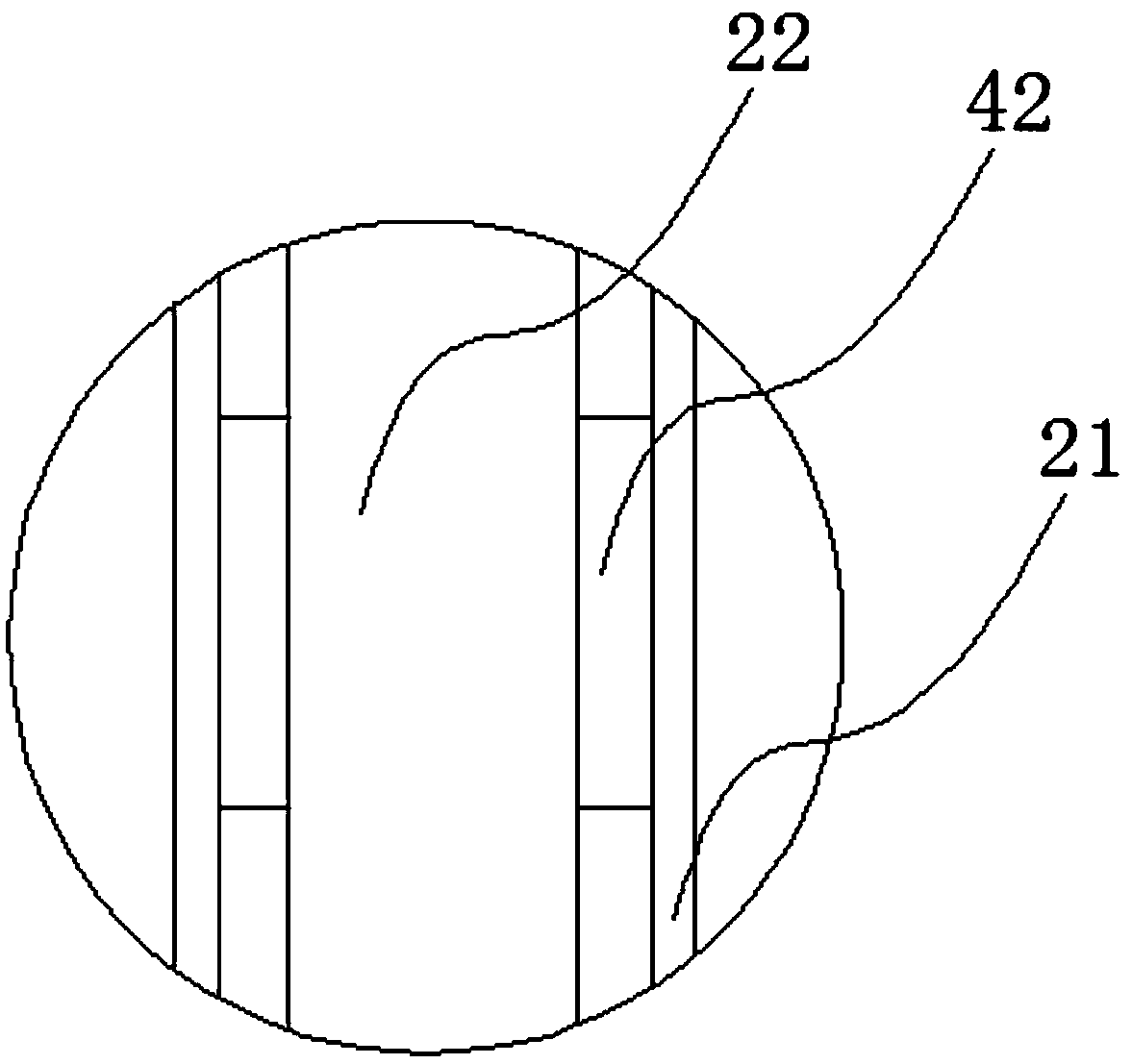
[0019] The left side outer wall of support plate 11 is welded with a hollow tube 21 along the length direction of support plate 11, and a cylinder 22 is movably arranged in the inner chamber of hollow tube 21, and the top of cylinder 22 is fixed with a tube extending to ...


PUM


Abstract

The invention discloses a medical ear washing device which comprises a base, a support plate and a container, wherein the support plate is fixed at the top of the base; the container is used for containing normal saline; a hose communicated with the inner cavity of the container is fixed at the bottom of the container; a washing tube is fixed at an end of the hose; a control valve is mounted on the outer wall of the washing tube; a hollow tube is fixed on the outer wall of the left side of the support plate in a length direction of the support plate; a column body is moveably arranged in the inner cavity of the hollow tube; a connecting block which extends outside the hollow tube and is connected with the container is fixed at the top of the column body; a transverse plate is fixed on theouter wall of the right side of the support plate; a fixing base is fixed on the transverse plate; a rotating rod is rotationally arranged on the fixing base; a winding reel is fixed at one end of therotating rod; an L-shaped rocker rod is fixed at the other end of the rotating rod; a fixed pulley is mounted at the top of the support plate; a wire which winds cross the fixed pulley and is connected with the top of the column body is wound on the winding reel; a stripy groove in which the connecting block slides is formed in the outer wall of the hollow tube.

Description

technical field [0001] The invention relates to a medical ear irrigation device. Background technique [0002] Existing medical ear irrigation devices on the market generally include a container for containing physiological saline, a flexible hose connected to the inner cavity of the container is fixed at the bottom of the container, and an irrigation tube is fixed at the end of the flexible hose. This medical ear irrigation device The structure is simple, but the speed of the water jetting out of the flushing pipe cannot be adjusted, and the practicability is poor. Contents of the invention [0003] The problem to be solved by the present invention is to provide a highly practical and easy-to-use medical ear irrigation device. [0004] In order to solve the above technical problems, the technical solution adopted by the present invention is: a medical ear irrigation device, including a base, a support plate fixed on the top of the base, a container for holding physiologi...

Claims


Application Information

Patent Timeline
Patent Type & Authority Applications(China)
IPC IPC(8): A61H35/00A61M3/02
CPCA61H35/00A61H2205/027A61M3/02A61M2210/0662
Inventor 王回芳
Owner 王回芳
Why Eureka
Try Eureka