
Assembling and welding clamp

A welding fixture and clamping unit technology, applied in the field of welding fixtures, can solve problems such as increased manufacturing cost, and achieve the effects of convenient welding operation and low cost

Pending Publication Date: 2018-11-02
BAOTOU NORTH VENTURE
View PDF0 Cites 3 Cited by
  • Summary
  • Abstract
  • Description
  • Claims
  • Application Information

AI Technical Summary

Problems solved by technology

At the same time, in order to avoid the increase in product manufacturing costs caused by the use process, the welding fixture must be designed in a form that requires no energy consumption

Method used


Image

  • Assembling and welding clamp
  • Assembling and welding clamp
  • Assembling and welding clamp

Examples


Embodiment 1

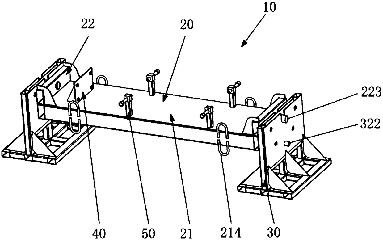
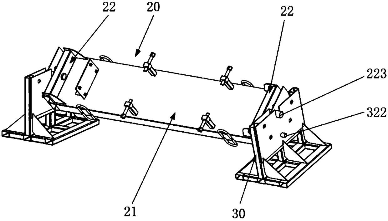
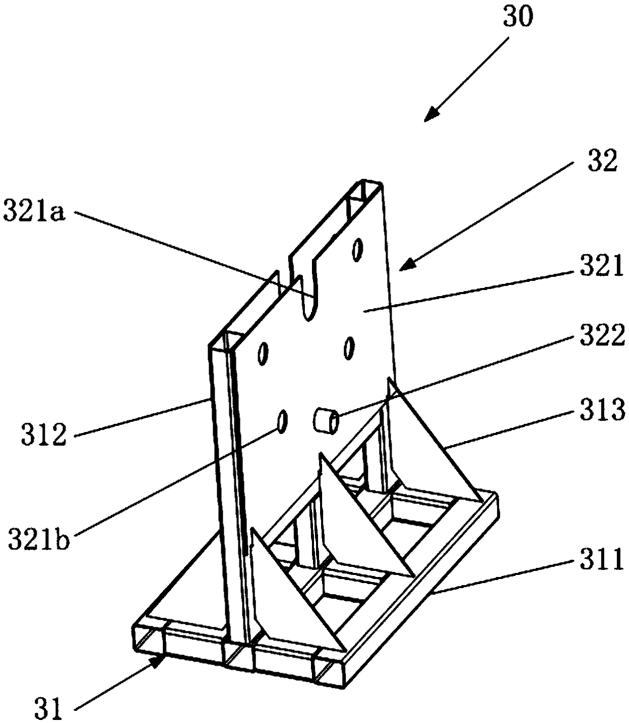
[0030] figure 1 It is an overall three-dimensional schematic diagram of the platform operation unit of the welding fixture of the present invention in a horizontal state. figure 2 It is an overall three-dimensional schematic diagram of the platform operation unit of the welding fixture of the present invention in an inclined state. Figure 4 It is a three-dimensional schematic diagram of the platform operation unit of the welding fixture of the present invention.

[0031] Such as figure 1 As shown, the welding jig 10 is used for assembling and welding small and medium-sized steel structures. unit.

[0032] The platform operation unit 20 is supported by the rotation support unit 30 in a manner of being erected on the left and right rotation support units 30 , and there is a space for the platform operation unit 20 to rotate on the lower side of the platform operation unit 20 . The platform working unit 20 has a working platform 21 for performing welding work, and left and ...

Embodiment 2

[0044] Except for the following technical content, all the other conditions are the same as in Embodiment 1: the disposition angular interval of the support plate positioning holes 224b of the rotating support plate 224 is set corresponding to the positioning plate positioning holes 321b of the rotating positioning plate 321, and the plurality of support plate positioning holes 221b of the rotating support plate 224 The arrangement angular intervals of the plate positioning holes 224b are 30°, and the arrangement angular intervals of the plurality of positioning plate positioning holes 321b of the rotation positioning plate 321 are 30°.

Embodiment 3

[0046] Except for the following technical content, all the other conditions are the same as in Embodiment 1: the disposition angular interval of the support plate positioning hole 224b of the rotating support plate 224 does not correspond to the positioning plate positioning hole 321b of the rotating positioning plate 321, and the plurality of support plate positioning holes 321b of the rotating support plate 224 The arrangement angular interval of the plate positioning holes 224b is 30°, and the arrangement angular interval of the plurality of positioning plate positioning holes 321b of the rotation positioning plate 321 is 45°.


PUM


Abstract

The invention discloses an assembling and welding clamp. The assembling and welding clamp comprises a platform working unit, a rotary supporting unit for supporting the platform working unit and a clamping unit mounted on the platform working unit, wherein the platform working unit is provided with a working platform for carrying out assembling and welding work and rotating mechanisms mounted at two end sides of the working platform; the rotating mechanisms and the working platform can be integrally supported through the rotary supporting unit in a manner of rotating relative to the rotary supporting unit, and can be positioned in a specified angle in a rotation range of the rotating mechanisms and the working platform. The assembling and welding clamp disclosed by the invention can be used for carrying out assembling and welding production on medium-size and small-size steel structure parts in a low-cost and high-reliability manner.

Description

technical field [0001] The invention relates to a welding jig, in particular to a multi-angle turning welding jig. Background technique [0002] The welding fixture is an indispensable tooling equipment in the production and manufacturing. Its main function is to facilitate the assembly positioning and welding flip in the production process of the product, so as to improve the assembly efficiency and ensure the welding quality. In recent years, with the development of the national economy and the advancement of manufacturing technology, in the assembly and welding of large steel structures, manufacturing companies generally choose special assembly tooling for positioning and clamping of product assembly processes, and special welding equipment for The product welding process is reversed to ensure the flat welding requirements of product assembly and related welds. [0003] The investment in special tooling equipment and energy consumption such as wind, water, and electricit...

Claims


Application Information

Patent Timeline
IPC IPC(8): B23K37/04
CPCB23K37/0443
Inventor 王灵艳姜建召张建军张志远张帅李景元庞建新刘建新
Owner BAOTOU NORTH VENTURE
Learn More