
Composite die structure

A composite mold and template technology, applied in metal processing and other directions, can solve the problems of low efficiency, turning processing efficiency, large waste, etc., and achieve the effect of high efficiency and compact structure

Active Publication Date: 2018-11-02
LANDING GEAR ADVANCED MFG
View PDF4 Cites 2 Cited by
  • Summary
  • Abstract
  • Description
  • Claims
  • Application Information

AI Technical Summary

Problems solved by technology

Compression molding can achieve "exactly the same", after heating, pressurization, heat preservation, pressure holding, trimming process, the efficiency is low; turning processing efficiency is high, waste is large, and the quality is unstable due to human factors; generally, one working stroke of a composite mold can only Processing one specification, low efficiency and large waste

Method used


Image

  • Composite die structure
  • Composite die structure
  • Composite die structure

Examples


Embodiment Construction

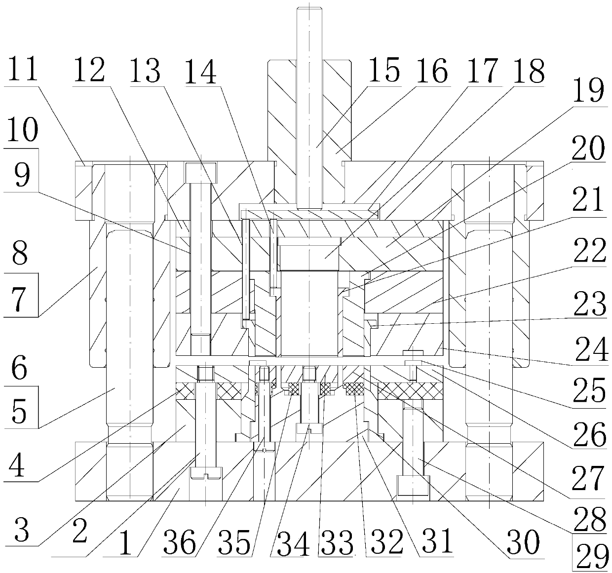
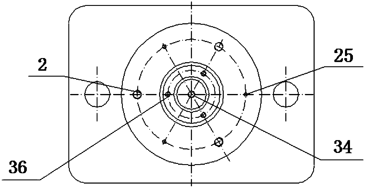
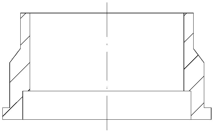
[0036] Such as figure 1 - Figure 16 As shown, the composite mold structure of the present invention includes an upper mold and a lower mold that are arranged oppositely.

[0037] The upper mold includes an upper template 11, an upper mold backing plate 12, a small punch splint 19, a large punch splint 22 and a large gasket shape blanking die 24 stacked from top to bottom, and the upper template 11, the upper mold backing plate 12. The small punch splint 19, the large punch splint 22 and the large washer-shaped blanking die 24 are fixedly connected into one body by three screws 9 and two pins 10, and the middle part of the upper template 11 is set and installed on the press The mold handle 16 on the slide block, the middle part of the mold handle 16 is sleeved with a punching rod 15, the bottom of the punching rod 15 is provided with a top plate 17, and the top plate 17 is embedded in the bottom of the upper template 11. The middle part of the small punch splint 19 is sandwi...


PUM


Abstract

A composite die structure comprises an upper die and a lower die. A die handle (16) is arranged on an upper die plate of the upper die. A knockout rod (15) with an ejector plate (17) arranged at the bottom is arranged in the middle of the die handle in a sleeved manner. A small gasket inner hole convex die (18) is arranged in a small convex die clamp plate. A large gasket inner hole convex die (20) is arranged in a large convex die clamp plate. The large gasket inner hole convex die and the small gasket inner hole convex die stretch to the bottom of a large gasket shape blanking concave die (24). A large part pushing device (23) and a small part pushing device (21) are arranged on the outer sides of the bottoms of the large gasket inner hole convex die and the small gasket inner hole convex die correspondingly. A long ejector pin (13) is arranged between the ejector plate and the large part pushing device. A short ejector pin (14) is arranged between the ejector plate and the small part pushing device. Motion space which is at least equal to the height of a gasket is arranged between the ejector plate and the upper die plate. A large convex-concave die (30) is clamped in a lower die clamp plate of the lower die. A small convex-concave die (31) is arranged in the large convex-concave die. The top of the large convex-concave die and the top of the small convex-concave die extendto be flushed with the top of a discharging plate, and an elastic base plate and an ejection ring are arranged on the upper portions of inner cavities of the large convex-concave die and the small convex-concave die correspondingly.

Description

technical field [0001] The invention relates to a gasket processing mold, in particular to a composite mold structure used for stamping gaskets of landing gear sealing systems and processing gaskets of two specifications in one punching process. Background technique [0002] In the production of landing gear, the most difficult bottleneck problem to solve is the sealing of each system, which is mainly guaranteed by sealing rings and gaskets. After the landing gear is installed, the size of each matching gap greatly affects the service life of the sealing ring and the friction force during the movable seal; under the pressure of the working medium, the sealing ring part is squeezed into the matching gap between the shaft and the hole, The friction increases, and the sealing ring wears and causes oil leakage; the method of installing the gasket is used to protect the sealing ring, and the gasket bears the pressure. The commonly used landing gear gasket material is polytetrafl...

Claims


Application Information

Patent Timeline
Patent Type & Authority Applications(China)
IPC IPC(8): B26F1/44B26D7/18
CPCB26D7/1818B26F1/44
Inventor 白亚玲姚志强樊智敏李博沈勇李涛杨怀中陈学虎
Owner LANDING GEAR ADVANCED MFG
Learn More