
Inter-locked building block capable of being additionally provided with reinforcing steel bar of retaining wall of protecting slope

A retaining wall block and block technology, applied in the direction of coastline protection, etc., can solve the problems of hidden safety hazards, difficult construction, insufficient design, etc., to achieve enhanced reliability and stability, low construction difficulty and cost, and improve plant quality. The effect on survival

Pending Publication Date: 2018-11-02
阮思忠
View PDF0 Cites 0 Cited by
  • Summary
  • Abstract
  • Description
  • Claims
  • Application Information

AI Technical Summary

Problems solved by technology

Dry soil can play a stabilizing effect, but after a long period of rain and the filling soil absorbs water, the density of the soil will increase and sink, and gravity will be on the block. If the friction between the geogrid and the block If the force is not enough, the geogrid will slip out of the block, causing the wall to collapse, posing a safety hazard
Moreover, the construction of horizontal limit with bolts is difficult and labor-intensive, which also increases the cost.
For this reason, the defect of insufficient design of the original retaining wall blocks must be overcome, and it has become an urgent task to provide a new type of retaining wall blocks

Method used


Image

  • Inter-locked building block capable of being additionally provided with reinforcing steel bar of retaining wall of protecting slope
  • Inter-locked building block capable of being additionally provided with reinforcing steel bar of retaining wall of protecting slope
  • Inter-locked building block capable of being additionally provided with reinforcing steel bar of retaining wall of protecting slope

Examples


Embodiment Construction

[0046] In order to more clearly describe the embodiments of the present invention or the technical solutions in the prior art, the following will briefly introduce the drawings that are used in the embodiments. Apparently, the drawings in the following description are only some embodiments of the present invention, and those skilled in the art can also obtain other drawings according to these drawings without creative efforts.

[0047]When describing the embodiments of the present invention, the terms "vertical", "transverse", "upper", "lower", "front", "rear", "left", "right", "vertical", " The orientation or positional relationship expressed by "horizontal", "top", "bottom", "inner" and "outer" is based on the orientation or positional relationship shown in the relevant drawings, which are only for the convenience of describing the utility model and simplifying the description. It is not intended to indicate or imply that the device or element referred to must have a particu...


PUM


Abstract

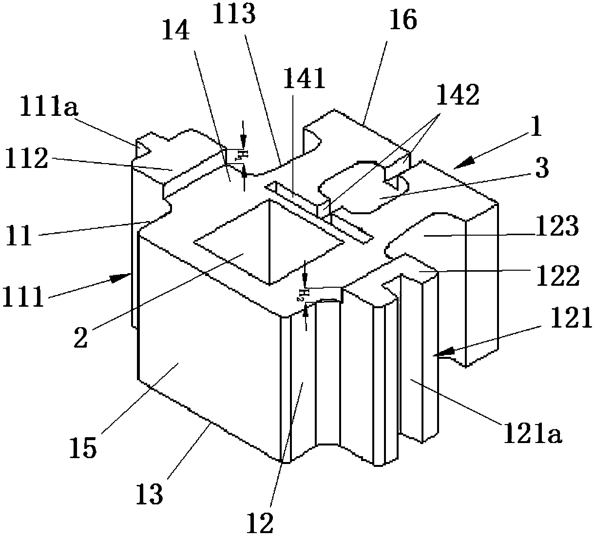
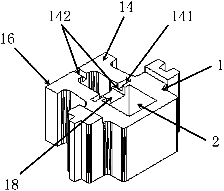
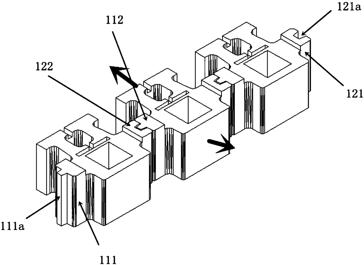
The invention relates to an inter-locked building block capable of being additionally provided with reinforcing steel bar of a retaining wall of a protecting slope. The building block specifically comprises a first corner surface on a first surface, a second corner surface, a bottom plane on a third surface, an upper plane on a fourth surface, a wall space on a fifth surface and a back wall on a sixth surface. A first side arm is arranged on the first corner surface, a second side arm is arranged on the second corner surface, a boss higher than the upper plane is arranged on the end part of the first side arm, a trapezoidal raised head from the upper plane to the bottom plane all the way is arranged on the edge of the boss, a boss higher than the upper plane is also arranged on the end part of the second side arm, a trapezoidal raised head from the upper plane to the bottom plane 13 all the way is arranged on the edge of the boss, the building block is provided with a first front through hole and a second back through hole penetrating the bottom plane on the third surface and the upper plane on the fourth surface, a first groove and a second groove are formed in the wall between afront hole and a back hole, and half of the wall between the first front through ole and the second back through hole is penetrated, so that filled soil in the front hole and filled soil behind the wall are connected, and therefore, the plant survival rate in the hole is improved.

Description

technical field [0001] The invention relates to a retaining wall block whose upper and lower sides are plane, in particular to an ecological slope retaining wall block which can be interlocked with each other and can be provided with reinforcing bars. Background technique [0002] The special geographical location determines that quite a few retaining walls with different lengths and heights will be built in seawalls, river banks, low mountain slope protection, embankments, field reclamation, and hilly areas. A retaining wall built with stones is costly, and the construction period is long, and it is not ecological. Construction with concrete blocks is simple and convenient, and the cost is low, so concrete blocks are widely used. There are two types of products that have been disclosed on the market. These two types of products have defects of insufficient stability and safety hazards. The traditional retaining wall blocks have disclosed self-embedded retaining wall blocks...

Claims


Application Information

Patent Timeline
Patent Type & Authority Applications(China)
IPC IPC(8): E02B3/14
CPCE02B3/14
Inventor 阮思忠
Owner 阮思忠
Learn More