Pneumatic double-acting pump

A double-acting pump and pneumatic technology, applied in variable capacity pump components, pumps, piston pumps, etc., can solve the problems of loss of pump function, damage to fluid quality, energy-consuming components, etc., to achieve the adjustment of fluid delivery flow rate, convenient fluid Delivery flow rate, the effect of precision fluid delivery flow rate

Inactive Publication Date: 2018-11-02
STPAPE CO LTD
View PDF6 Cites 3 Cited by
  • Summary
  • Abstract
  • Description
  • Claims
  • Application Information

AI Technical Summary

Problems solved by technology

[0003] The fluid thrust of the existing pump is caused by the centrifugal force generated by the blades driven by the motor. In order to obtain the centrifugal force required to pressurize the fluid, the motor speed must be maintained at a high speed; however, the high-speed operation of the motor not only consumes energy and causes wear of the components, but also It will also increase the internal temperature of the pump and damage the fluid quality. If you want to reduce the motor speed to reduce the damage rate of the pump and the damage to the fluid, you find that the low-speed motor cannot drive the blades to generate centrifugal force to push the fluid, and the pump function will be lost.
Therefore, the existing pumps are only suitable for fast delivery and fluids with lower requirements for delivery quality, but cannot be used for thick fluids that need to be delivered at a slow speed, and the existing pumps can only be used for single fluid delivery at a time, and do not have the ability to Effects such as fluid transport in more than two areas

Method used


Image

  • Pneumatic double-acting pump
  • Pneumatic double-acting pump

Examples


Embodiment Construction

[0040] In order to enable a more complete and clear disclosure of the technical means of the present invention and the effects it can achieve, the detailed description is as follows. Please also refer to the disclosed drawings and figure numbers:

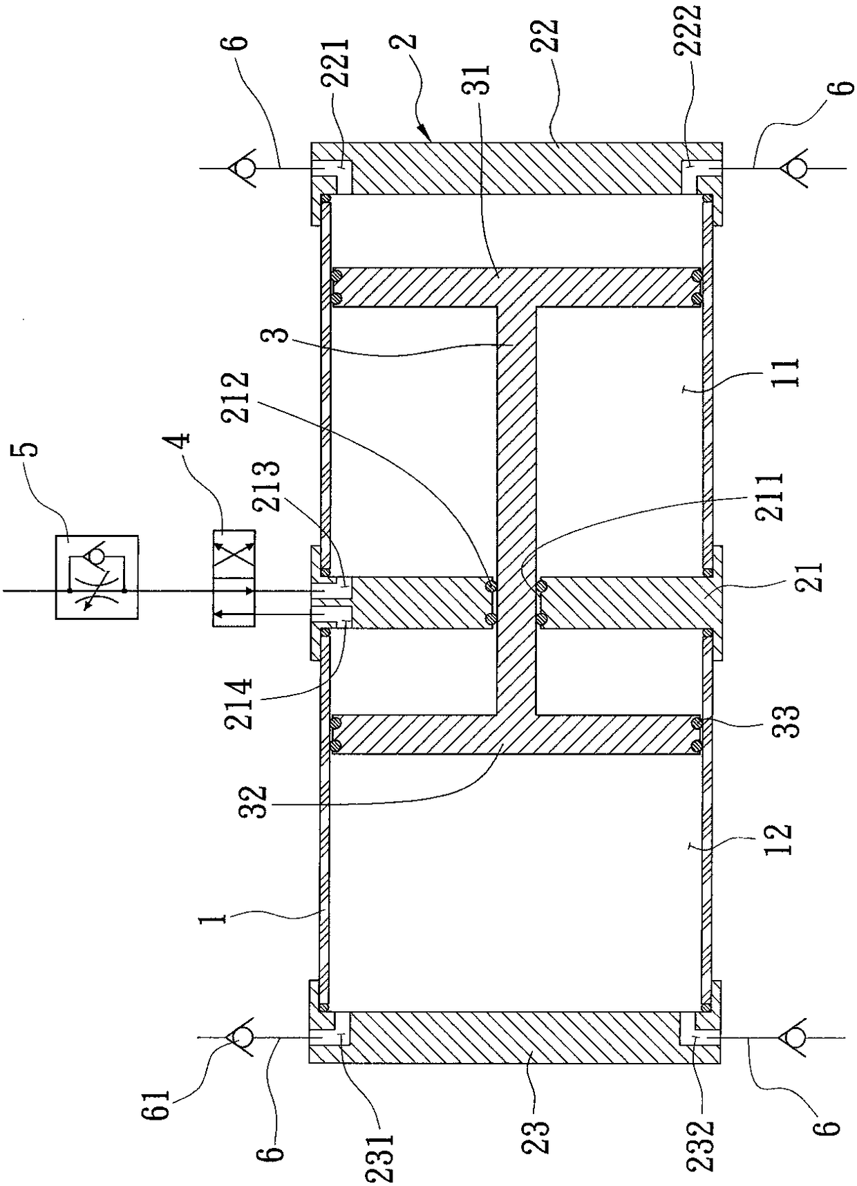
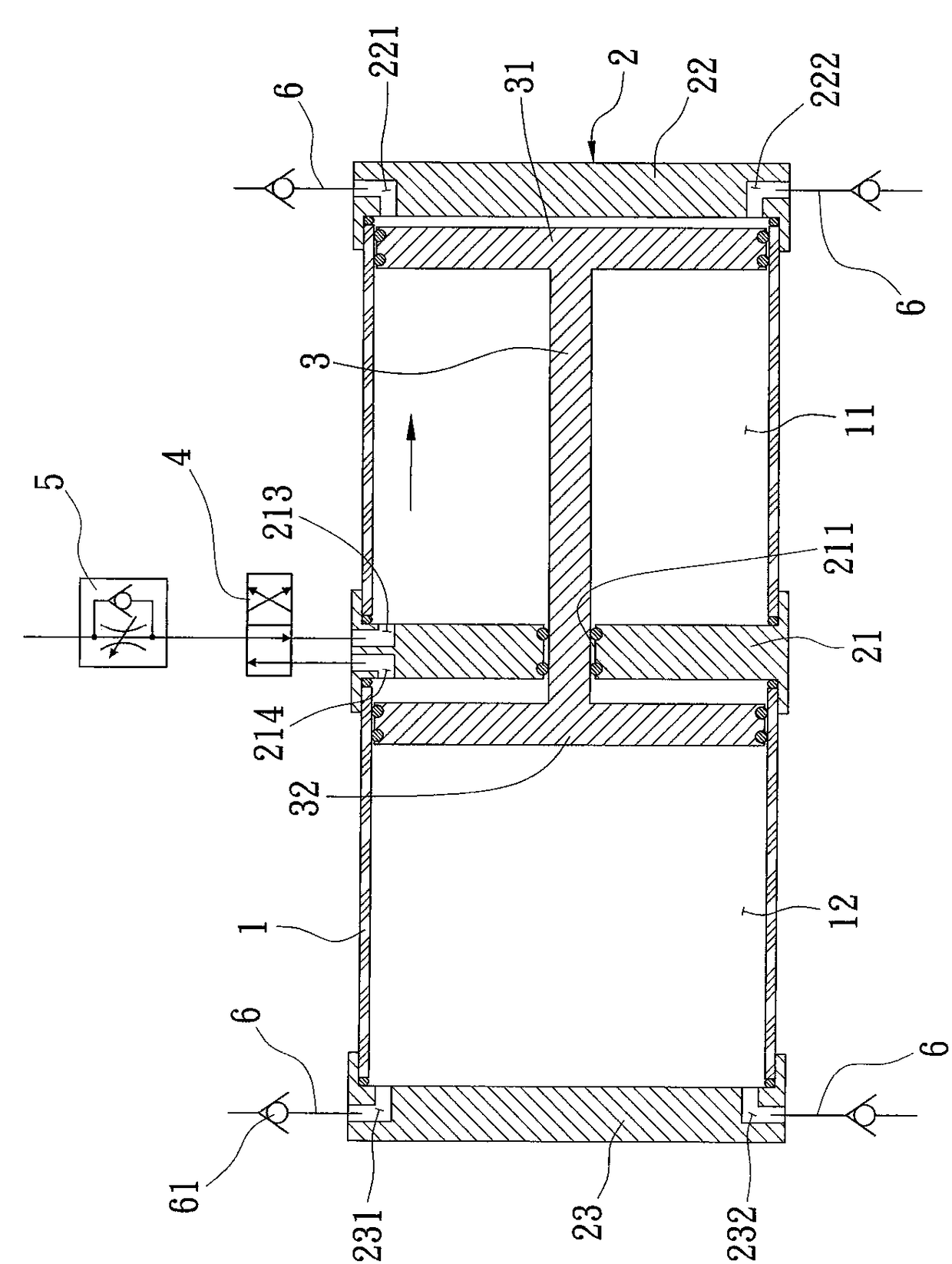
[0041] First, see figure 1 As shown, it is a pneumatic double-action pump of the present invention, which is provided with a hollow pump main body 1, and the hollow pump main body 1 is divided into at least two chambers by at least three partitions 2, and the partition between the two chambers Three partitions 2 respectively constitute the two end walls of the two chambers, the present invention defines the three partitions 2 as the first partition 21, the second partition 22 and the third partition 23, and the two chambers are defined as the second partition A chamber 11 and a second chamber 12, and make the partition 2 between the first chamber 11 and the second chamber 12 be the first partition 21, and make the first chamber and ...


PUM


Abstract

The invention relates to a pneumatic double-acting pump. A pump main body is divided into two chambers by three partition plates; a piston rod penetrate through the first partition plate located between the two chambers; a first piston and a second piston arranged at the two ends of the piston rod are positioned in the two chambers correspondingly; an inlet of the first partition plate is sequentially connected with a switching valve and an air flow valve through pipelines; the other ends, connected with the first partition plate, of the two chambers are assembled with the second partition plate and the third partition plate correspondingly; and an inlet and an outlet of the second partition plate and an inlet and an outlet of the third partition plate are connected with working pipelinescorrespondingly. Therefore, by switching the valve position of the switching valve, the pistons in the two chambers can be pressurize and output fluid in the chambers of the pistons, in addition, thepiston feeding speed can be controlled through the air flow valve, thereby achieving the effects of outputting the fluid in at least two different regions at a time, and movably adjusting the fluid delivery frequency and flow rate, etc.

Description

technical field [0001] The present invention relates to a pneumatic double-acting pump, especially a pneumatic double-acting pump capable of outputting fluids in at least two different areas at one time, and can easily and accurately adjust fluid delivery frequency and flow rate. Background technique [0002] Existing pumps are mainly composed of a body, a motor, and blades. The motor is installed on one side of the body, and the drive shaft connected to the motor penetrates into the body to be assembled with the blades located in the body. When the motor is activated, the fluid will be drawn into the body from the inlet on one side of the body, and the blades will be used to pressurize the fluid to be output from the outlet of the body. In this way, the fluid delivery pressure will be increased, and the fluid will flow from the lower part to the lower part. Push high. [0003] The fluid thrust of the existing pump is caused by the centrifugal force generated by the blades ...

Claims


Application Information

Patent Timeline
Patent Type & Authority Applications(China)
IPC IPC(8): F04B9/129F04B49/22F04B53/10F04B53/14
CPCF04B9/129F04B49/225F04B53/10F04B53/14
Inventor 李圣聪
Owner STPAPE CO LTD
Why Eureka
Try Eureka