Full-automatic flatness detection mechanism for cross beam of intelligent desk

A detection mechanism and fully automatic technology, which is applied in the direction of mechanical roughness/irregularity measurement, etc., can solve the problems of limited effect, trouble, and the inability to adjust the horizontal position of the detection block, etc., to achieve good effect and wide application range

Inactive Publication Date: 2018-11-02
DONGGUAN LIANZHOU INTPROP OPERATION MANAGEMENT CO LTD
View PDF5 Cites 0 Cited by
  • Summary
  • Abstract
  • Description
  • Claims
  • Application Information

AI Technical Summary

Problems solved by technology

[0002] When the existing table body is being processed, a horizontal beam is generally provided between the two adjacent table legs, and to detect whether the table legs of the table body are vertical, it is possible to detect whether the two horizontal beams are flat. The way is to manually use vertical wooden strips or rulers for leveling detection. It is determined whether there is a gap between the vertical wooden strips or rulers and the side wall of the transverse beam with the naked eye. The effect is limited. Straight bars or rulers are inaccurate and cumbersome;
[0003] Now some specific detection mechanisms have the ability to move to the detection block for detection, but the horizontal position of the detection block cannot be adjusted, so that the height of the table leg side support beam of the table body to be detected must correspond to the detection block, which greatly affects its use. Range, unable to meet the detection of table leg side support beams of different heights

Method used


Image

  • Full-automatic flatness detection mechanism for cross beam of intelligent desk
  • Full-automatic flatness detection mechanism for cross beam of intelligent desk

Examples


Embodiment Construction

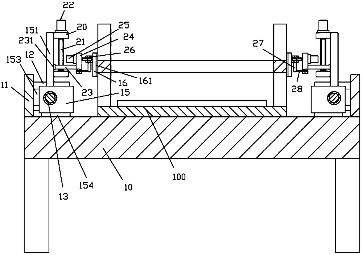
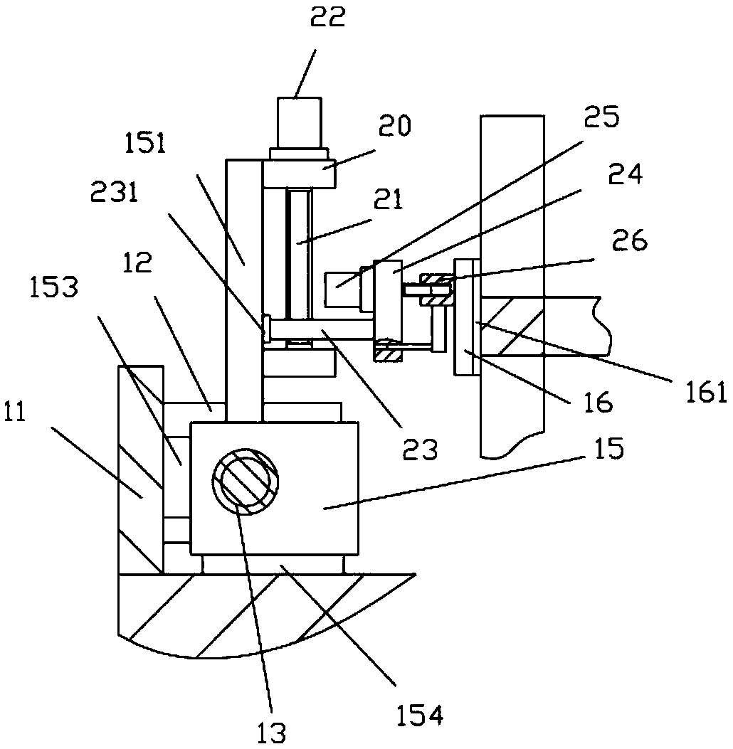
[0018] Examples, see e.g. Figure 1 to Figure 2 As shown, a crossbeam automatic flatness detection mechanism of an intelligent table body includes a detection frame 10, vertical plates 11 are fixed on the left and right sides of the top surface of the top plate of the detection frame 10, and vertical plates 11 Support plates 12 are fixed on the inner side walls of the front end and the rear end, and the two ends of the drive screw 13 are hinged on the two support plates 12 on the same side, and one of the support plates 12 is fixed with a drive motor 14, the output shaft of the drive motor 14 It is a spline shaft, and the spline shaft is inserted into the spline hole provided at one end of the transmission screw rod 13. The moving block 15 is screwed on the transmission screw rod 13, and the top surface of the moving block 15 is fixed with an upper support plate 151, and the upper support plate 151 is fixed with adjustable horizontal plates 20 on the inner side walls of the to...


PUM


Abstract

The invention discloses a full-automatic flatness detection mechanism for a cross beam of an intelligent desk, and the mechanism comprises a detection rack. The left and right sides of the top surfaceof a top plate of the detection rack are fixedly provided with vertical plates, and the inner walls of the front and rear ends of the vertical plates are fixedly provided with support plates. Two ends of a transmission screw are hinged to two support plates at the same side, wherein one support plate is fixedly provided with a drive motor. An output shaft of the drive motor is a spline shaft, andthe spline shaft is inserted in a spline hole at one end of the transmission screw. A moving block is connected to the transmission screw in a threaded manner, and the top surface of the moving blockis fixedly provided with an upper support plate. The inner walls of the top and lower part of the upper support plate are fixedly provided with adjustment lateral plates. The detection mechanism canenable a flat block to be adjusted vertically and horizontally so as to enable the flat block to be attached to side walls of a support beam of legs of desks at different heights, and the flat block automatically moves, thereby facilitating the manual observation. Moreover, a person does not need to hold the flat block, so the detection mechanism is very convenient, is wide in application range, and is good in effect.

Description

Technical field: [0001] The invention relates to the technical field of smart home processing equipment, in particular to a fully automatic flatness detection mechanism for a beam of a smart table body. Background technique: [0002] When the existing table body is being processed, a horizontal beam is generally provided between the two adjacent table legs, and to detect whether the table legs of the table body are vertical, it is possible to detect whether the two horizontal beams are flat. The way is to manually use vertical wooden strips or rulers for leveling detection. It is determined whether there is a gap between the vertical wooden strips or rulers and the side wall of the transverse beam with the naked eye. The effect is limited. Straight bars or rulers are inaccurate and cumbersome; [0003] Now some specific detection mechanisms have the ability to move to the detection block for detection, but the horizontal position of the detection block cannot be adjusted, s...

Claims


Application Information

Patent Timeline
IPC IPC(8): G01B5/28
CPCG01B5/28
Inventor 徐亚维
Owner DONGGUAN LIANZHOU INTPROP OPERATION MANAGEMENT CO LTD
Why Eureka
Try Eureka