
Multi-mode synchronous triggering control circuit and method thereof in automatic ultrasonic detecting system

A technology of ultrasonic detection and synchronous triggering, which is applied in the direction of program control, computer control, general control system, etc., can solve the problems of wasting time and cumbersome operation process, and achieve the advantages of strong versatility, convenient operation and avoiding the delay of trigger pulse Effect

Active Publication Date: 2018-11-02
CHINA WEAPON SCI ACADEMY NINGBO BRANCH
View PDF7 Cites 5 Cited by
  • Summary
  • Abstract
  • Description
  • Claims
  • Application Information

AI Technical Summary

Problems solved by technology

Since the coaxial signal line needs to be replaced when the three trigger mode settings are switched, this brings a lot of tediousness to the actual operation process of the inspectors and wastes time

Method used


Image

  • Multi-mode synchronous triggering control circuit and method thereof in automatic ultrasonic detecting system
  • Multi-mode synchronous triggering control circuit and method thereof in automatic ultrasonic detecting system
  • Multi-mode synchronous triggering control circuit and method thereof in automatic ultrasonic detecting system

Examples


Embodiment Construction

[0021] The present invention will be further described in detail below in conjunction with the accompanying drawings and embodiments.

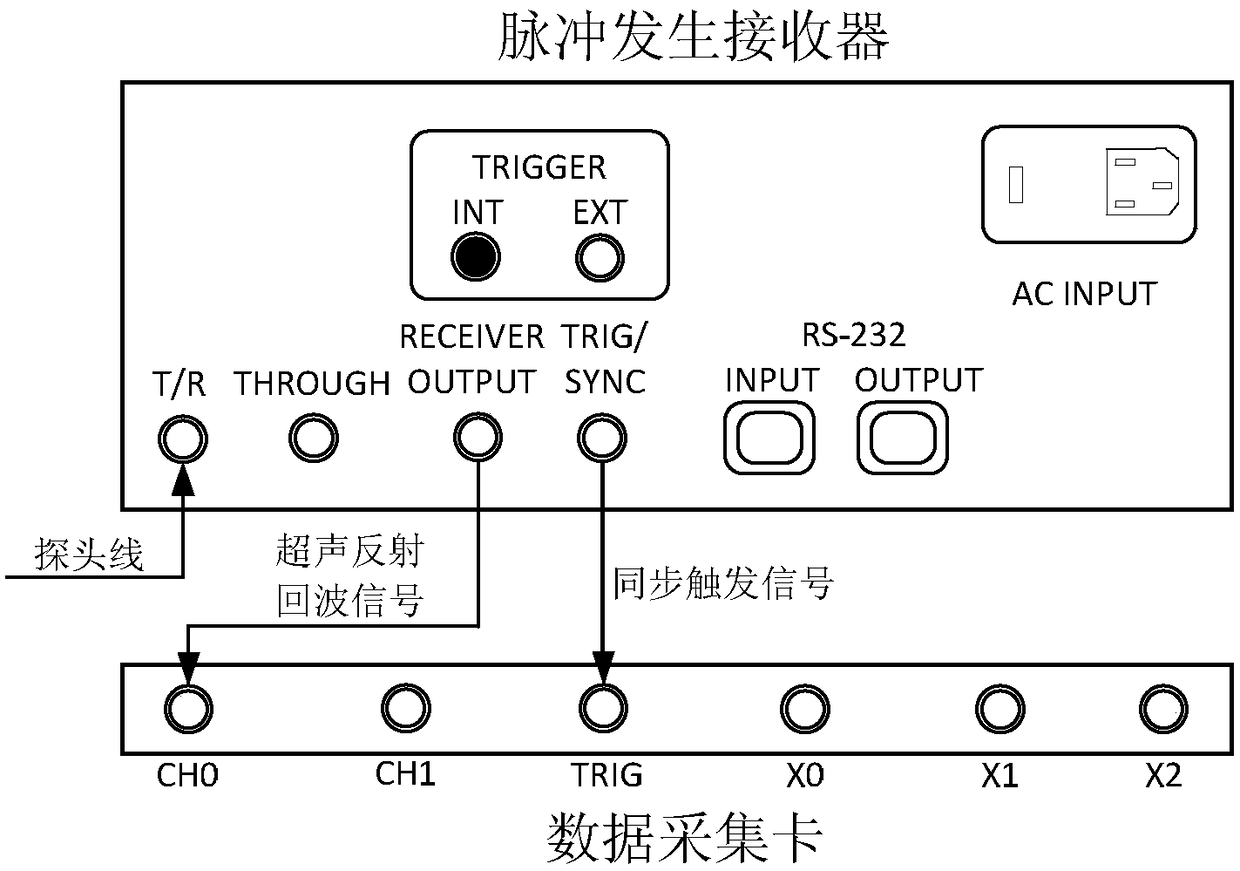
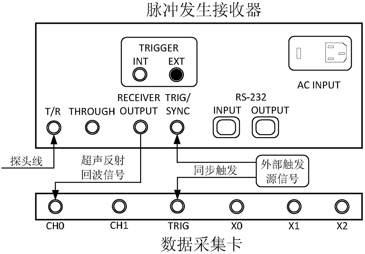
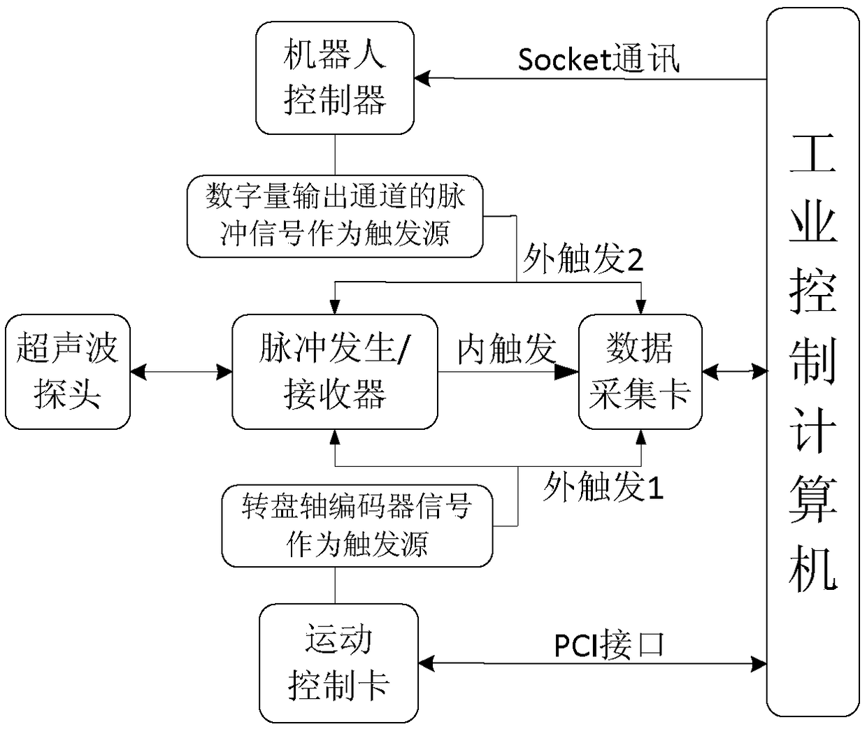
[0022] Such as Figure 1~4 As shown, a multi-mode synchronous trigger control circuit in an automated ultrasonic detection system includes a trigger mode switching circuit, the input terminals of the trigger mode switching circuit are respectively the robot controller and the turntable shaft motion control card, and the trigger mode switching circuit includes relay K1, relay K2, relay K3 and relay K4, relay K1 and relay K2 control the robot controller through the trigger circuit, and are used to realize the external trigger mode when performing bow-shaped C-scan imaging on the plane workpiece; the two ends of the normally open contact K31 of the relay K3 are respectively Connect the OC1 pin of the turntable axis motion control card and the pulse generator, and connect the two ends of the normally open contact K32 of the relay K3 to the OC2 pin...


PUM

PropertyMeasurementUnit
electrical resistanceaaaaaaaaaa

Abstract

The invention discloses a multi-mode synchronous triggering control circuit in an automatic ultrasonic detecting system, which is characterized by comprising a trigger mode switching circuit, whereina robot controller and a rotary table axis motion control card are arranged at the input ends of the trigger mode switching circuit; the trigger mode switching circuit comprises a relay K1, a relay K2, a relay K3 and a relay K4; the relay K1 and the relay K2 control the robot controller through a trigger circuit, and are used for implementing an external trigger mode in arcuate C-scan imaging; therelay K3 is used for implementing the external trigger mode in spiral C-scan imaging; the relay K4 is used for implementing an internal trigger mode; and the switching of different modes of the trigger mode switching circuit is realized by controlling the closing and opening of the relay K1, the relay K2, the relay K3 and the relay K4 through upper computer software. The invention further discloses a control method which is characterized in that the automatic switching of the ultrasonic detecting system is controlled by an upper computer; and the control circuit is simple in structure, convenient to operate, and strong in universality.

Description

technical field [0001] The invention relates to a control circuit for multi-mode synchronous triggering in an automatic ultrasonic detection system, and also relates to a control method for the control circuit. Background technique [0002] In the automatic ultrasonic testing system, when the pulse generator and the PCI bus data acquisition card receive a synchronous short pulse trigger signal of 3~5V, the pulse generator generates a high-voltage spike excitation to cause the ultrasonic probe to produce an inverse piezoelectric effect and emit ultrasonic waves. Acquisition of ultrasonic echo signals and A / D conversion are realized by the data acquisition card. According to the trigger signal source, it is usually divided into two synchronous trigger methods, namely internal trigger and external trigger. [0003] When the internal trigger mode is used for automatic detection, the pulse generator's own oscillation circuit usually outputs a trigger pulse with a fixed repetitio...

Claims


Application Information

Patent Timeline
Patent Type & Authority Applications(China)
IPC IPC(8): G01N29/22G01N29/06G05B19/042
CPCG01N29/0654G01N29/22G01N2291/023G01N2291/26G05B19/042
Inventor 张荣繁倪培君齐子诚郭智敏李红伟唐盛明郑颖左欣王晓燕乔日东张维国
Owner CHINA WEAPON SCI ACADEMY NINGBO BRANCH
Learn More