
Rotary impact current prevention switch device based on magnetorheological effect

A magneto-rheological effect and current switch technology, applied in the direction of magnetic/electric field switch, electric switch, circuit, etc., can solve the problems of unsuitable for large power circuit, short service life, poor carrying capacity, etc., to avoid large pulse current, improve conduction efficiency, and selectivity

Active Publication Date: 2018-11-02
CHINA THREE GORGES UNIV
View PDF4 Cites 5 Cited by
  • Summary
  • Abstract
  • Description
  • Claims
  • Application Information

AI Technical Summary

Problems solved by technology

However, the structure of the rotary switch has the following technical defects: there are bumps and contacts on the contact bridge, the upper surfaces of the central terminal and the peripheral terminal are flat, and the bumps and contacts are in contact with the central terminal and the peripheral terminal respectively To form an electrical connection, since the bump is in point contact with the central terminal, and the contact is also in point contact with the circumferential terminal. During use, the resistance at the two electrical connection points is relatively large. When the circuit current is small, use It is acceptable, but when the current passing through the contact bridge is large, a high temperature will be generated at the two electrical contacts between the contact bridge and the central terminal and the circumferential terminal, and the heat will be transferred to the plastic base, causing deformation or aging of the base , poor carrying capacity, short service life, not suitable for use on circuits with high power, which limits its scope of application

Method used


Image

  • Rotary impact current prevention switch device based on magnetorheological effect
  • Rotary impact current prevention switch device based on magnetorheological effect
  • Rotary impact current prevention switch device based on magnetorheological effect

Examples


Embodiment Construction

[0031] Principle analysis:

[0032] The magnetorheological material based on magnetic metal microparticles is a suspension formed by mixing magnetic metal microparticles and all non-conductive and non-magnetically permeable liquids (or colloids).

[0033] Under the action of an external magnetic field, the magnetic metal microparticles in the magnetorheological fluid will form solidified and thicker "chain bundles" along the direction of the magnetic field. This phenomenon has been verified by scientific experiments by many research groups. Such as literature: "Zhao Li, Bu He Battelle, Tian Yan. Research on magnetorheological fluid [J]. Chemical Engineer, 2001 (06): 19-20." Recorded. Such experimental results indirectly prove that the magnetic metal microparticles will form a conductive "path" in the direction parallel to the applied magnetic field, because a large number of conductive metal microparticles gather into long chains and solidify to form a conductive "chain bundle...


PUM


Abstract

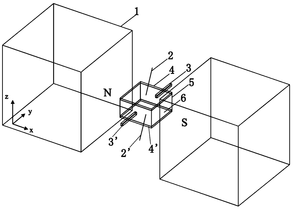
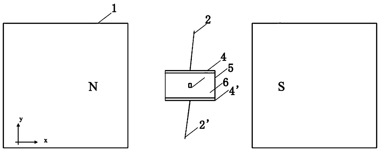
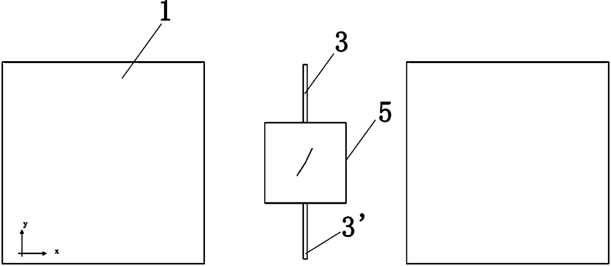
The invention relates to a rotary impact current prevention switch device based on a magnetorheological effect, which comprises an enclosed insulator square box, wherein the enclosed insulator squarebox is arranged between two magnets; and a magnetorheological material is packaged in the enclosed insulator square box. Both upper and lower surfaces of the enclosed insulator square box respectivelyare metal electrodes, and the metal electrodes are connected with wires. Four front, rear, left and right surfaces of the enclosed insulator square box are insulation surfaces, wherein the front andrear surfaces are respectively connected with rotating shafts. The enclosed insulator square box is a flat square body. The rotary impact current prevention switch device based on the magnetorheological effect, which is disclosed by the invention, regulates a magnetic field direction applied by the outside by controlling a rotating angle of the magnetorheological material part so as to fulfill theswitch on-off aim, and regulates an on-off speed by controlling a rotating speed. The rotary impact current prevention switch device has the advantages of simple structure, stability, reliability, good reversibility and the like.

Description

technical field [0001] The invention is a rotary anti-shock current switch device based on the magneto-rheological effect, which is suitable for electronically controlled or computer-controlled switching systems of high-voltage lines. Background technique [0002] At present, the rotary switches on the market can be seen everywhere, but due to the defects in the design of the existing rotary switches, the disadvantages of inflexibility and poor contact during the rotation process, and even the damage of the device due to the inrush current, thus giving some configurations Machines with rotary switches bring some inconvenience, especially in high-voltage circuits where such contact switches pose potential safety hazards. [0003] Rotary switches are widely used in various circuits. The working process of traditional rotary switches is to use a rotatable central shaft to drive the contact bridge to connect or disconnect the terminals to realize the on-off of the circuit. Multi...

Claims


Application Information

Patent Timeline
IPC IPC(8): H01H36/00
CPCH01H36/00
Inventor 朴红光贾高萌王志豪黄悦华杨雄波谭新玉潘礼庆李定林陈满黄彦良
Owner CHINA THREE GORGES UNIV
Learn More