Motor with high application stability

A technology with stable performance and electric motors, which is applied in the field of electric motors, can solve problems such as waste of time and manpower, damage to the rotating shaft, and falling off of the nuts that fix the electric motor, and achieve the effects of saving installation time, scientific and reasonable structure, and safe and convenient use

Inactive Publication Date: 2018-11-02
张志通
View PDF0 Cites 1 Cited by
  • Summary
  • Abstract
  • Description
  • Claims
  • Application Information

AI Technical Summary

Problems solved by technology

[0003] The present invention provides a motor with high stability in use, which can effectively solve the problem in the above-mentioned background art that during the handling of the motor, since the rotating shaft is exposed outside, the rotating shaft is likely to collide with the outside and cause damage to the rotating shaft, which in turn affects the normal use of the motor. ; When installing the rear end cover of the motor, because the rear end cover cannot be positioned accurately, the installation of the rear end cover is more troublesome, and it takes a long time for comparison to be able to realize the installation of the rear end cover, which is wasteful Time and manpower; during the use of the motor, due to the rotation of the rotor, the motor will generate a lot of vibration. If the motor is not damped in time, the motor will be displaced, which will cause the motor to be placed unstable; After use, the mounting base and the fixing plate will be bonded due to corrosion, and the motor cannot be disassembled. Moreover, after long-term use, the nuts fixing the motor will fall off, resulting in the problem that the motor is not firmly fixed.

Method used


Image

  • Motor with high application stability
  • Motor with high application stability
  • Motor with high application stability

Examples


Embodiment

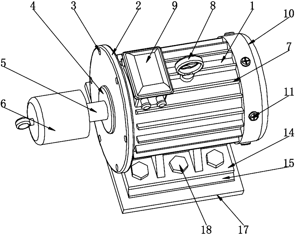
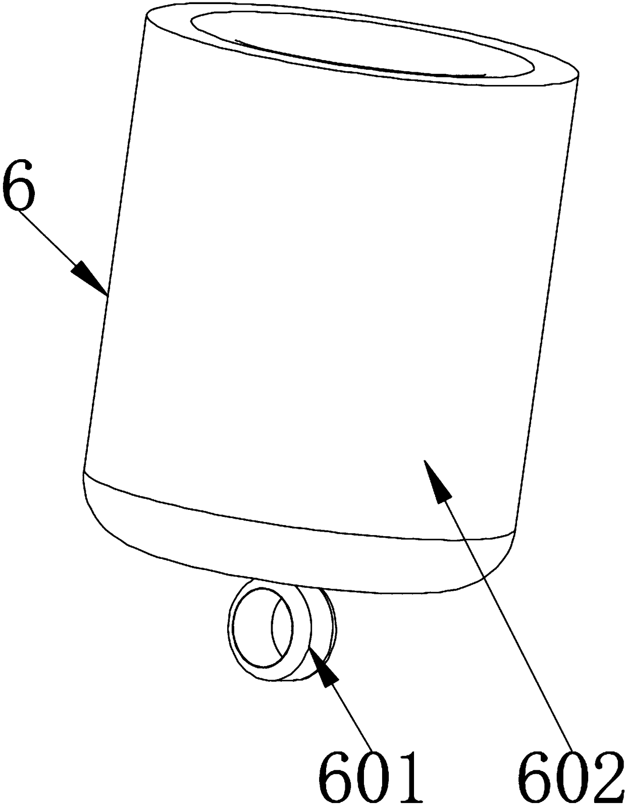
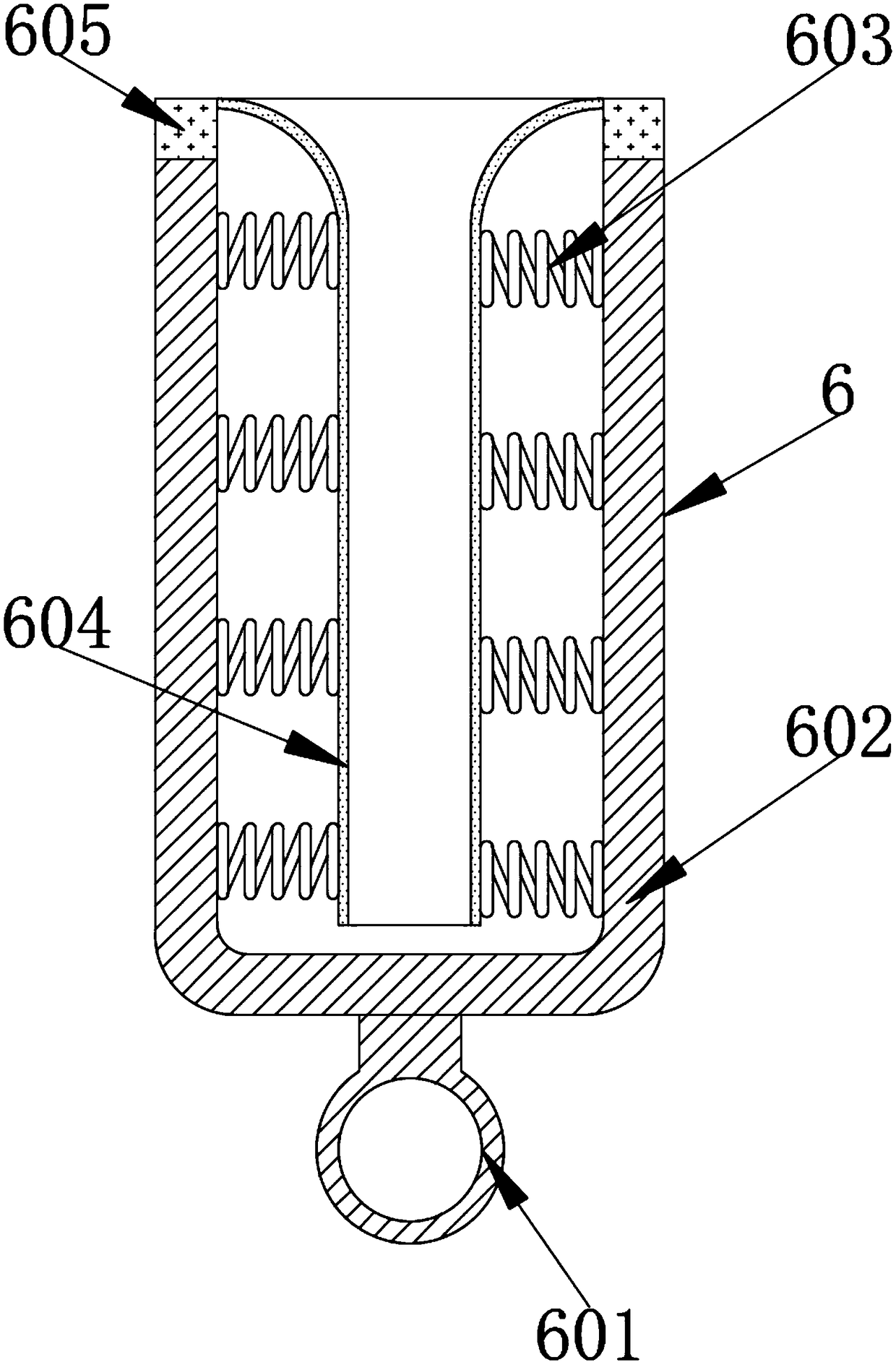
[0034] Example: such as Figure 1-9As shown, the present invention provides a technical solution, a motor with high stability in use, including a motor housing 1, one end of the motor housing 1 is provided with a front end cover 2, and the outer side of the front end cover 2 is provided with a first fixing screw Hole 3, the middle part of one side of the front end cover 2 is welded with a fixed iron block 4, the middle part of one side of the fixed iron block 4 is installed with a rotating shaft 5, and the outer side of the rotating shaft 5 is sleeved with a protective component 6, in order to facilitate the protection of the rotating shaft 5 during transportation and prevent The rotating shaft 5 is damaged due to collision during transportation. The inner diameter of the protective assembly 6 is equal to the outer diameter of the rotating shaft 5. The protective assembly 6 includes a pull ring 601, a protective shell 602, a fixed spring 603, a protective rubber sleeve 604 and ...


PUM


Abstract

The invention discloses a motor with high application stability. The motor comprises a motor shell, wherein a front end cover is arranged at one end of the motor shell, cooling plates are arranged atouter sides of the motor shell at equal distance, and a hanging ring is fixedly arranged at a middle part of a top end of the motor shell by a thread. The motor is scientific and reasonable in structure and is safe and convenient to use; a pull ring, a protection shell, a fixed spring, a protection rubber sleeve and a fixed magnet are arranged; fixed installation and disassembly of the protectionshell are conveniently achieved by the pull ring; a rotation shaft can be effectively prevented from being collided with a foreign matter during the carrying process by the protection shell, and the normal application of the rotation shaft is effectively ensured; the impact applied to the rotation shaft can be effectively reduced by the fixed spring and the protection rubber sleeve when the foreign matter is collided with the protection shell, and the protection on the rotation shaft during the carrying process of the motor is further guaranteed; and a protection assembly can be fixedly installed by the fixed magnet and is prevented from falling off.

Description

technical field [0001] The invention relates to the technical field of motors, in particular to a motor with high stability in use. Background technique [0002] The motor is a device that converts electrical energy into mechanical energy. It uses a energized coil to generate a rotating magnetic field and acts on the rotor to form a magnetoelectric force. The motor is divided into DC motors and AC motors according to the power supply used. The motors in the power system are large Part of it is an AC motor, which can be a synchronous motor or an asynchronous motor. The motor is mainly composed of a stator and a rotor. The direction of the current-carrying wire in the magnetic field is related to the direction of the current and the direction of the magnetic induction line. The working principle of the motor is that the magnetic field affects the current. The effect of force makes the motor rotate. In the prior art, the use of the motor has the following defects: during the ha...

Claims


Application Information

Patent Timeline
Patent Type & Authority Applications(China)
IPC IPC(8): H02K5/04H02K5/24H02K5/18H02K5/20H02K5/22
CPCH02K5/04H02K5/18H02K5/20H02K5/225H02K5/24
Inventor 张志通
Owner 张志通
Why Eureka
Try Eureka