
Tail gas treatment device for chemical equipment

A technology for exhaust gas treatment and chemical equipment, applied in chemical instruments and methods, dispersed particle separation, dispersed particle filtration, etc., can solve problems such as inconvenient installation and replacement of filter screens, inability to stably fix filter plates, and time-consuming and labor-intensive replacement. To achieve the effect of strong practicability, time saving and convenient use

Inactive Publication Date: 2018-11-06
龚卫珍
View PDF0 Cites 3 Cited by
  • Summary
  • Abstract
  • Description
  • Claims
  • Application Information

AI Technical Summary

Problems solved by technology

[0003] During the operation of chemical equipment, exhaust gas will be generated, and the exhaust gas will be directly discharged into the atmosphere, which will cause serious pollution to the environment. It is necessary to filter the exhaust gas and then discharge it. However, it is inconvenient to install and replace the filter when the existing exhaust gas is filtered. After the filter has been used for a period of time, it is time-consuming and labor-intensive to replace, and the efficiency is low. Moreover, when filtering the exhaust gas, the filter plate cannot be stably fixed, and it is easy to shake when subjected to external force. Therefore, we propose a chemical Equipment tail gas treatment device to solve the above problems

Method used


Image

  • Tail gas treatment device for chemical equipment
  • Tail gas treatment device for chemical equipment
  • Tail gas treatment device for chemical equipment

Examples


Embodiment Construction

[0021] The following will clearly and completely describe the technical solutions in the embodiments of the present invention with reference to the accompanying drawings in the embodiments of the present invention. Obviously, the described embodiments are only some, not all, embodiments of the present invention.

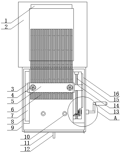
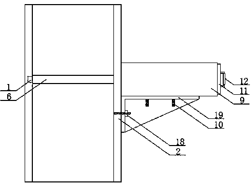
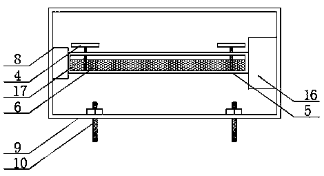
[0022] refer to Figure 1-4 , a chemical equipment tail gas treatment device, comprising a discharge pipe 2 to facilitate the discharge of tail gas, a fixed box 9 is fixed on one side of the discharge pipe 2, a mobile device is jointly arranged between the opposite side walls in the fixed box 9, and a mobile device is provided on the mobile device There is a fixing device, one side of the fixing box 9 is provided with a first opening, one side of the discharge pipe 2 is provided with a second opening corresponding to the first opening, the first opening and the second opening are jointly provided with a filter plate 6, It is convenient to filter the exhaust gas. A li...


PUM


Abstract

The invention discloses a tail gas treatment device for chemical equipment. The device comprises a discharge pipeline, wherein one side of the discharge pipeline is fixedly provided with a fixed box,opposite side walls in the fixed box are jointly provided with a moving device, the moving device is provided with a fixing device, one side of the fixed box is provided with a first opening, one sideof the discharge pipeline is provided with a second opening corresponding to the first opening, a filter plate runs through the first opening and the second opening together, the side wall of one endin the discharge pipeline is provided with a limiting groove, and the limiting groove corresponds to one end of the filter plate. The tail gas treatment device for the chemical equipment has the advantages that the problem of inconvenient assembly and disassembly when the filter plate is replaced is solved, the assembly and disassembly efficiency is improved, a large amount of time is reduced, the problem that tail gas cannot be filtered due to the fact that the filter plate shakes easily when being subjected to an external force is also avoided, the practicability is high, the operation is simple, and the use is convenient.

Description

technical field [0001] The invention relates to the technical field of tail gas treatment, in particular to a chemical equipment tail gas treatment device. Background technique [0002] Chemical equipment is a part of chemical machinery. Chemical machinery consists of two parts. One is chemical machinery, which mainly refers to equipment such as fans, compressors, and various pumps for fluid transportation. The main components are moving machinery, generally called chemical engineering. machine. The second is that chemical equipment mainly refers to machinery whose components are static, such as separation equipment such as towers, containers, reactor equipment, etc., sometimes also called non-standard equipment. [0003] During the operation of chemical equipment, exhaust gas will be generated, and the exhaust gas will be directly discharged into the atmosphere, which will cause serious pollution to the environment. It is necessary to filter the exhaust gas and then discha...

Claims


Application Information

Patent Timeline
Patent Type & Authority Applications(China)
IPC IPC(8): B01D46/10B01D46/42
CPCB01D46/10B01D46/0005B01D46/4227
Inventor 龚卫珍
Owner 龚卫珍
Learn More