
Box cover for test tube rack and screw cap device for sample tube

A technology for test tube racks and sample tubes, which is applied in the field of capping devices for box covers and sample tubes, which can solve the problems of lack of quality, waste of manpower and material resources, and insufficient automation, and achieve the effect of improving the use efficiency

Pending Publication Date: 2018-11-06
佛山市德淙科学仪器有限公司
View PDF0 Cites 0 Cited by
  • Summary
  • Abstract
  • Description
  • Claims
  • Application Information

AI Technical Summary

Problems solved by technology

[0003] Before processing biological samples, the sample tube needs to be uncapped. During the whole process, the cover of the sample tube has no good place to place it, and the residual liquid on the cover is easy to drip and pollute the machine and others. tool
In addition, the steps of opening and closing the sample tube are still manual operations, which greatly wastes manpower and material resources, and the degree of automation is not enough. Moreover, the steps of opening and closing the sample tube are relatively independent of the entire LIMS, and the degree of informatization is not enough.

Method used


Image

  • Box cover for test tube rack and screw cap device for sample tube
  • Box cover for test tube rack and screw cap device for sample tube
  • Box cover for test tube rack and screw cap device for sample tube

Examples


Embodiment 1

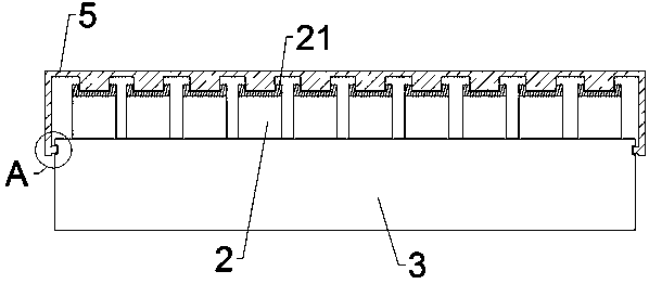
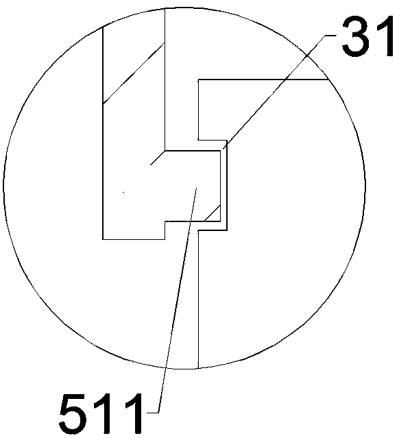
[0035] Such as Figure 1-3 As shown, a box cover 5 of a test tube rack 3 includes a box top 52 and at least a pair of box walls 51 oppositely arranged on the box top 52, and the box wall 51 is arranged on the inner side of one end away from the box top 52 There is a first fastening structure 511 adapted to the second fastening structure 31 on the test tube rack 3 .

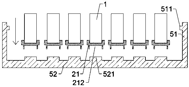
[0036] The box cover 5 is used for the test tube rack 3, and can be fastened on the upper part of the test tube rack 3 when it is not necessary to detect the biological sample. When the biological sample needs to be detected, as image 3 with 4 As shown, the box cover 5 can be reversed, the placement structure 521 faces upwards, and then the rotator 1 of the capping device places the lid 21 of the sample tube 2 after uncapping on the placement structure 521, which is not only convenient , and can prevent the residual liquid on the cover 21 from polluting the machine and other tools due to dripping, and it is not...

Embodiment 2

[0041] Such as Figure 5 Shown, a kind of capping device of sample tube 2 comprises:

[0042] main controller; and

[0043] At least one rotary drive mechanism, used to drive the rotating member 1 to rotate under the control command of the main controller, the input end of which is electrically connected to the output end of the main controller;

[0044] At least one rotary member 1 is used to rotate under the drive of the rotary drive mechanism, its input end is connected to the output end of the rotary drive mechanism, and the output end is connected with the cover 21 of the sample tube 2 in a manner to limit relative rotation. One-to-one connection.

[0045] The rotation driving mechanism of the capping device drives the rotating member 1 to rotate under the control command of the main controller, and after the rotating member 1 and the cover 21 of the sample tube 2 are plugged together, The relative rotation between the two can be limited, so the rotating member 1 will ...


PUM


Abstract

The invention discloses a box cover for a test tube rack and a screw cap device for a sample tube. The box cover comprises a box top and at least one pair of box walls arranged on the box top oppositeto each other, wherein a first fastening structure matched with a second fastening structure on the test tube rack is arranged on the inner side face of the end, which is far away from the box top, of the box walls; at least one placement structure matched with the bottom structure of the cover of the sample tube is arranged on the inner side face of the box top. The box cover can be fastened onto the test tube rack, and after the sample tube is uncovered, the cover of the sample tube can be placed in the box cover. The operation is convenient, remaining liquid on the cover can be prevented from contaminating the machine and other tools due to dropping, the screw cap device does not need to be occupied, and the service efficiency of the screw cap device is improved.

Description

technical field [0001] The invention relates to a LIMS system, in particular to a box cover of a test tube rack and a screw cap device for a sample tube. Background technique [0002] Laboratory Information Management System (LIMS) is an efficient integrated system that completes the collection, analysis, reporting and management of laboratory data and information through a combination of software and hardware. It is the cornerstone of biological service enterprises to achieve modernization, informatization and automation. [0003] Before processing biological samples, the sample tube needs to be uncapped. During the whole process, the cover of the sample tube has no good place to place it, and the residual liquid on the cover is easy to drip and pollute the machine and others. tool. In addition, the steps of opening and closing the sample tube are still manual operations, which greatly wastes manpower and material resources, and the degree of automation is not enough. More...

Claims


Application Information

Patent Timeline
IPC IPC(8): B01L9/00B01L9/06B01L3/00B01L3/14
CPCB01L3/50825B01L3/523B01L9/00B01L9/06B01L2200/02
Inventor 王权蔡颖鹏
Owner 佛山市德淙科学仪器有限公司
Learn More