
Paint spraying device for production and processing of furniture

A kind of furniture, the same technology, applied in the direction of spraying device, spraying room, etc., can solve the problems of wasting time, polluting the air, affecting the health of spraying workers, etc., to achieve the effect of improving work efficiency, convenient operation, and reducing limitations

Inactive Publication Date: 2018-11-06
安吉木博家居有限公司
View PDF0 Cites 2 Cited by
  • Summary
  • Abstract
  • Description
  • Claims
  • Application Information

AI Technical Summary

Problems solved by technology

During the production and processing of wooden doors, in order to increase the decorativeness and corrosion resistance of wooden doors, a layer of paint will be sprayed on the surface of wooden doors. The traditional painting method is usually by manual spraying. Processors will directly put the wooden doors on the work surface Then use a spray gun to paint the wooden door. After spraying the front of the wooden door, let it dry for a period of time. After the paint solidifies, the processing personnel will turn the wooden door over by hand and spray the back of the wooden door. A good front needs to be dried for a period of time, so that after the paint on the surface of the door is solidified, the processing personnel can turn over the back of the wooden door, so it is a waste of time. When the workers spray paint on the door panels, there is no special space for workers to spray paint. At the same time, the residual paint sprayed spreads and pollutes the air, affecting the health of painting workers

Method used


Image

  • Paint spraying device for production and processing of furniture
  • Paint spraying device for production and processing of furniture
  • Paint spraying device for production and processing of furniture

Examples


Embodiment Construction

[0023] The following will clearly and completely describe the technical solutions in the embodiments of the present invention with reference to the accompanying drawings in the embodiments of the present invention. Obviously, the described embodiments are only some, not all, embodiments of the present invention.

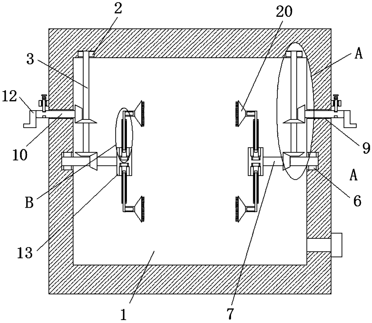
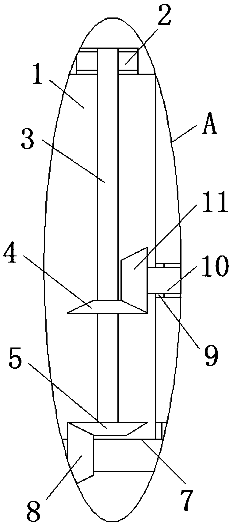
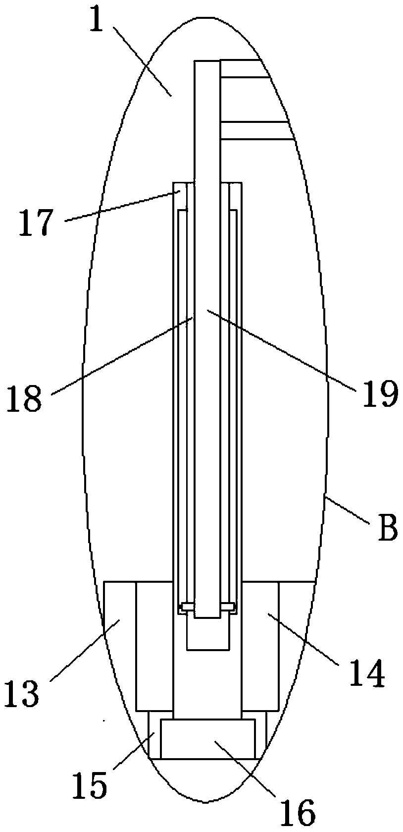
[0024] refer to Figure 1-3 , a paint spraying device for furniture production and processing, including a paint spray box 1 set as a hollow structure, two first rotating grooves 2 are provided on the top inner wall of the paint spray box 1, and two first rotating grooves 2 are installed in rotation The first rotating shaft 3, and the outer fixed cover of the first rotating shaft 3 is provided with the first bevel gear 4, and the bottom end fixed cover of the first rotating shaft 3 is provided with the second bevel gear 5, and on the both sides inner walls of the paint spraying box 1 A second rotating groove 6 is provided, and a rotating column 7 is installed in the ...


PUM


Abstract

The invention discloses a paint spraying device for production and processing of furniture. The paint spraying device comprises a paint spraying box, wherein the paint spraying box is of a hollow structure; two first rotating grooves are formed in the inner wall of the top of the paint spraying box; first rotating shafts are rotatably arranged in the two first rotating grooves; first conical gearsare arranged at the outer sides of the first rotating shafts in a fixing and sleeving manner; second conical gears are arranged at the bottoms of the first rotating shafts in a fixing and sleeving manner; second rotating grooves are formed in the inner walls of the two sides of the paint spraying box; rotating columns are rotatably arranged in the two second rotating grooves; and third conical gears are arranged at the outer sides of the rotating columns in a fixing and sleeving manner. The paint spraying device is simple in structure and convenient to operate; the body of the paint sprayingdevice can be rotated rapidly and conveniently and meanwhile can be adjusted angularly, so that the body of the paint spraying device has a relatively large paint spraying range on a door, the limitations of the body of the paint spraying device are reduced, and the working efficiency is improved; and the paint spraying device protects workers and reduces the influence on the health of paint spraying workers.

Description

technical field [0001] The invention relates to the technical field of paint spraying devices, in particular to a paint spraying device for furniture production and processing. Background technique [0002] Doors, that is, wooden doors, are widely used in civil, commercial and residential buildings. During the production and processing of wooden doors, in order to increase the decorativeness and corrosion resistance of the wooden doors, a layer of paint is sprayed on the surface of the wooden doors. The traditional painting method is usually by manual spraying, and the processing personnel will directly put the wooden doors on the work Then use a spray gun to spray paint on the wooden door. After spraying the front of the wooden door, let it dry for a period of time. After the paint solidifies, the processing personnel will turn the wooden door over by hand and spray the back of the wooden door. A good front needs to be dried for a period of time, so that after the paint on...

Claims


Application Information

Patent Timeline
Patent Type & Authority Applications(China)
IPC IPC(8): B05B16/00B05B13/04B05B12/16
CPCB05B16/00B05B12/16B05B13/0421
Inventor 毕魏杰
Owner 安吉木博家居有限公司
Learn More