
Round pipe cutting and end face grinding integrated machine

An all-in-one machine and round tube technology, applied in the direction of pipe shearing device, shearing device, other manufacturing equipment/tools, etc., can solve the problems of increasing labor cost, cutting human body, wasting time, etc., and achieving the effect of reducing manpower and time

Inactive Publication Date: 2018-11-06
李达
View PDF9 Cites 32 Cited by
  • Summary
  • Abstract
  • Description
  • Claims
  • Application Information

AI Technical Summary

Problems solved by technology

[0003] The round pipe cannot be put into use directly after the cutting machine completes the cutting. It is thought that there will be some burrs on the end face of the cut round pipe. If the burrs are not treated, the welding may not be sufficient or the burrs may cause the human body to be cut, which may cause diseases. , all the cut round tubes will be sent to the grinder to grind all the burrs before they can be used
[0004] However, after each cut, it will be sent to the grinding machine for grinding, which will waste time in the middle of the transfer, and will also increase the cost of workers, so a kind of equipment that integrates cutting and grinding is needed.

Method used


Image

  • Round pipe cutting and end face grinding integrated machine
  • Round pipe cutting and end face grinding integrated machine
  • Round pipe cutting and end face grinding integrated machine

Examples


Embodiment Construction

[0022] Below in conjunction with accompanying drawing and embodiment of description, specific embodiment of the present invention is described in further detail:

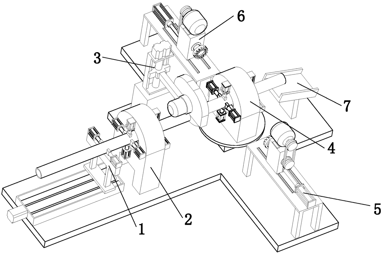
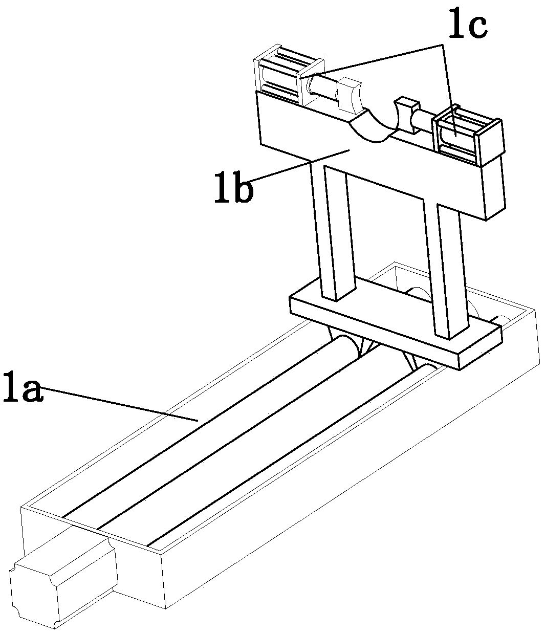
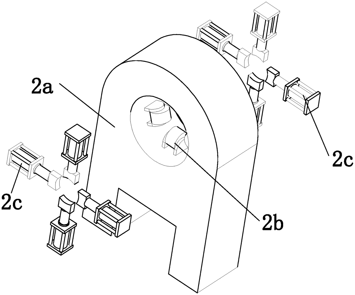
[0023] refer to Figure 1 to Figure 6 A round pipe cutting and end face grinding machine shown in the figure includes a bottom plate, and also includes a feeding assembly 1, a first clamping assembly 2, a cutting assembly 3, a second clamping assembly 4, a first grinding assembly 5 and a second grinding assembly Assembly 6, the second clamping assembly 4 includes a rotary table 4a, a second fixed seat 4b, a second pulley 4c and several second clamping cylinders 4d, the rotary table 4a includes a rotary motor, a motor mounting shell 4a2 and a turntable 4a3, The motor mounting shell 4a2 is installed on the base plate, the rotating motor is arranged inside the motor mounting shell 4a2 and the output end is set upwards, the rotating disk 4a3 is connected to the output end of the rotating motor in a horizontal state, the...


PUM


Abstract

The invention relates to the field of cutting and grinding machines, in particular to a round pipe cutting and end face grinding integrated machine. The round pipe cutting and end face grinding integrated machine comprises a bottom plate, and further comprises a feeding assembly, a first clamping assembly, a cutting assembly, a second clamping assembly, a first grinding assembly and a second grinding assembly; the first clamping assembly is located on one side of the second clamping assembly and fixedly installed on the bottom plate; the cutting assembly is located between the first clamping assembly and the second clamping assembly and fixedly installed on the bottom plate; the feeding assembly is located at the feeding end of the first clamping assembly and fixedly installed on the bottom plate; the feeding assembly, the first clamping assembly, the cutting assembly and the second clamping assembly are sequentially arranged in a linear state; the first grinding assembly is fixedly installed on the bottom plate, and the output end faces the second clamping assembly; the second grinding assembly is fixedly installed on the bottom plate, and the output end faces the output end of the first grinding assembly; the first grinding assembly, the second clamping assembly and the second grinding assembly are linearly arranged; and manpower cost is reduced.

Description

technical field [0001] The invention relates to the field of cutting and grinding machines, in particular to an integrated machine for cutting and grinding of round pipes. Background technique [0002] In general production and processing, round pipes are needed. After the round pipes are produced, they will be cut into different lengths according to different needs. The cutting machine is an indispensable processing machine in the production process of the mechanical processing manufacturing industry. Through the cutting machine, the The round tube is cut to the required size and length. [0003] The round pipe cannot be put into use directly after the cutting machine completes the cutting. It is thought that there will be some burrs on the end face of the cut round pipe. If the burrs are not treated, the welding may not be sufficient or the burrs may cause the human body to be cut, which may cause diseases. , all the cut round tubes will be sent to the grinder to grind al...

Claims


Application Information

Patent Timeline
Patent Type & Authority Applications(China)
IPC IPC(8): B23D21/00B23D33/02B23P23/04
CPCB23D21/00B23D33/02B23P23/04
Inventor 王立民
Owner 李达
Learn More