Rotor rivet removing device and operation method thereof

A rotor and guide rail technology, applied in metal processing and other directions, can solve the problems of time-consuming and laborious, operator cutting injury, low manual cutting efficiency, etc., and achieve the effect of convenient cutting, high work efficiency, and labor saving.

Pending Publication Date: 2018-11-06
芜湖联丰机电有限责任公司
View PDF0 Cites 0 Cited by
  • Summary
  • Abstract
  • Description
  • Claims
  • Application Information

AI Technical Summary

Problems solved by technology

The existing conventional method is to use manual cutting. However, the manual cutting is inefficient, time-consuming and laborious, and it is easy to cause the operator to cut off and get injured.

Method used


Image

  • Rotor rivet removing device and operation method thereof
  • Rotor rivet removing device and operation method thereof
  • Rotor rivet removing device and operation method thereof

Examples


Embodiment Construction

[0033] The specific embodiment of the present invention will be described in further detail by describing the embodiments below with reference to the accompanying drawings, the purpose is to help those skilled in the art to have a more complete, accurate and in-depth understanding of the concept and technical solutions of the present invention, and contribute to its implementation.

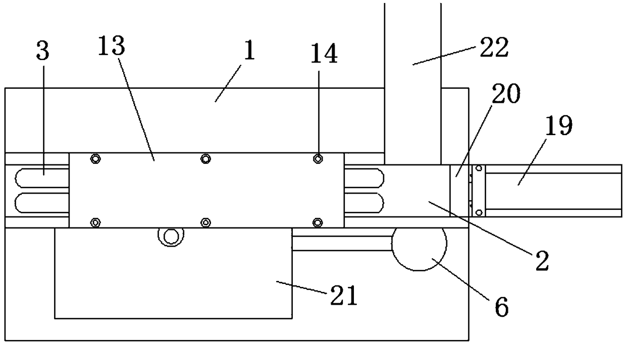
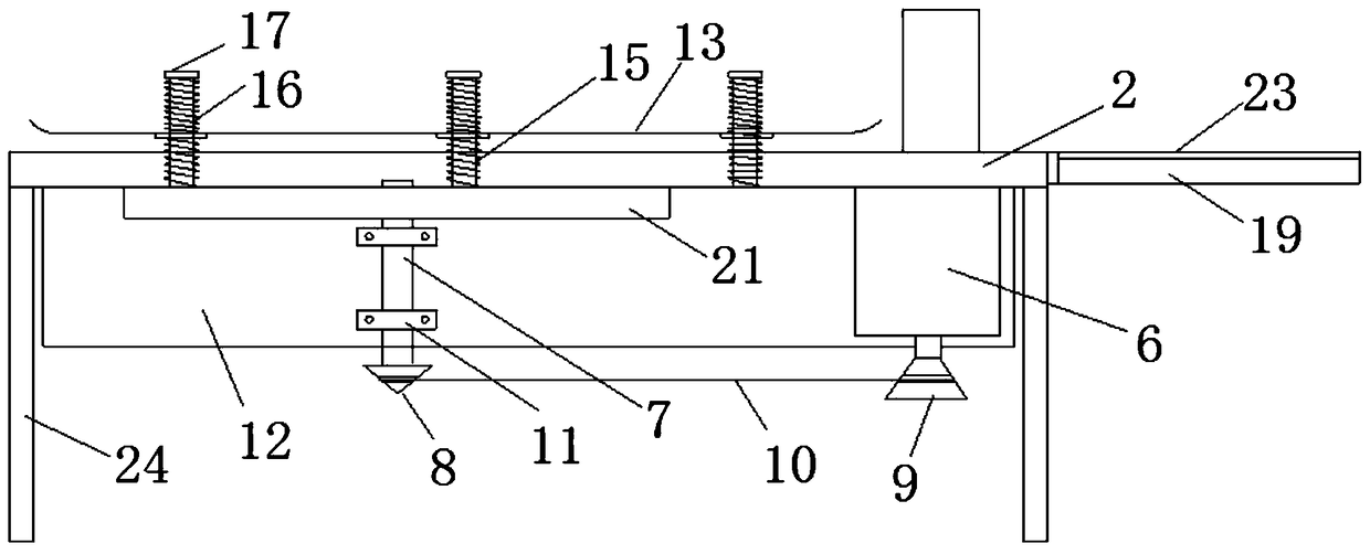
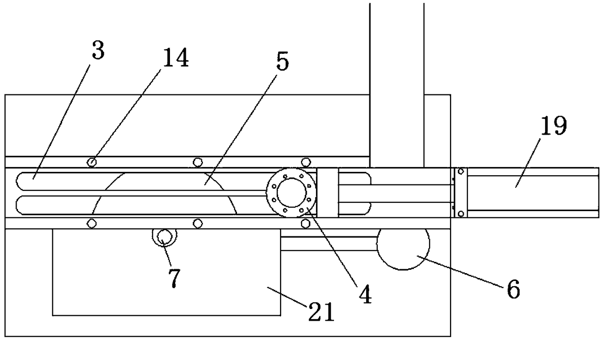
[0034] Such as Figure 1 to Figure 4 As shown, a rotor nail removing device has:

[0035] mesa1;

[0036] The cutting guide rail 2 is arranged on the table top 1, and the bottom surface of the cutting guide rail 2 and the table top 1 is provided with a cutting via hole 3;

[0037] A telescopic drive mechanism that drives the rotor 4 to slide on the cutting guide rail 2;

[0038] The limit capping mechanism of the rotor on the upper limit capping cutting guide rail 2 of the table top 1;

[0039] The cutting actuator is arranged under the platform 1 to cut the rivet 41 through which the rotor pa...


PUM


Abstract

The invention discloses a rotor rivet removing device and an operation method thereof. The rotor rivet removing device comprises a table surface, a cutting guide rail, a telescopic driving mechanism,a limiting, pressing and covering mechanism and a cutting executing mechanism, wherein the cutting guide rail is arranged on the table surface; the bottom surface, which makes contact with the table surface, of the cutting guide rail is provided with a cutting through hole; the telescopic driving mechanism is used for driving a rotor to slide on the cutting guide rail; the limiting, pressing and covering mechanism is arranged on the table surface and is used for limiting, pressing and covering the rotor positioned on the cutting guide rail; and the cutting executing mechanism is arranged belowthe table surface and is used for cutting a rivet, penetrating through the cutting through hole, of the rotor. The rotor rivet removing device disclosed by the invention is simple to operate, can beused for removing the rivet conveniently in a shearing way, needs no manual shearing operation, saves labor and is high in work efficiency.

Description

technical field [0001] The invention belongs to the technical field of motor rotor processing, and in particular relates to a rotor nail removing device and an operating method thereof. Background technique [0002] At present, due to the processing requirements of the motor rotor, it is often necessary to process a circle of rivets on the upper and lower end faces of the rotor. After the casting process of the motor rotor is completed, in order to meet the subsequent processing requirements of some motor rotors, it is necessary to cut off a certain length of rivets. The existing conventional method is to use manual pruning. However, manual pruning is inefficient, time-consuming and labor-intensive, and it is easy to cause injuries to operators. Contents of the invention [0003] The present invention aims to solve at least one of the technical problems existing in the prior art. Therefore, the present invention provides a rotor nail removal device and its operation meth...

Claims


Application Information

Patent Timeline
IPC IPC(8): B23D79/00B23Q7/00
CPCB23D79/00B23Q7/00
Inventor 李鹏胡传刚张峰峰
Owner 芜湖联丰机电有限责任公司
Why Eureka
Try Eureka