Supercharge Your Innovation With Domain-Expert AI Agents!

Digital controlled lathe clamping mechanism

A technology of clamping mechanism and CNC lathe, which is applied in the direction of clamping, positioning devices, metal processing machinery parts, etc., can solve the problems affecting the work of operators and operating hazards, and achieve the effect of convenient cleaning and reasonable design

Inactive Publication Date: 2018-11-06
江阴和港机械有限公司
View PDF3 Cites 0 Cited by
  • Summary
  • Abstract
  • Description
  • Claims
  • Application Information

AI Technical Summary

Problems solved by technology

[0002] Most of the existing CNC lathes need to press the parts on the CNC window by hand or directly with the tool when processing parts, which is dangerous to operate, and the existing CNC lathes will generate a lot of debris when clamping the parts. Debris left on the clamping mechanism interferes with the operator's work

Method used


Image

  • Digital controlled lathe clamping mechanism

Examples


Embodiment Construction

[0012] The present invention is described in further detail now in conjunction with accompanying drawing. These drawings are all simplified schematic diagrams, which only illustrate the basic structure of the present invention in a schematic manner, so they only show the configurations related to the present invention.

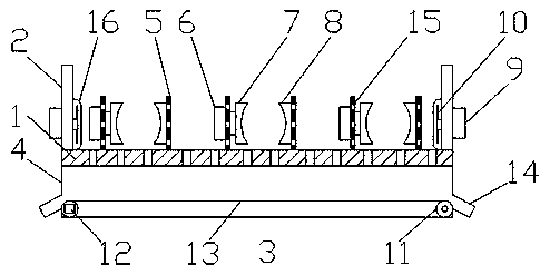
[0013] Such as figure 1 As shown, a clamping mechanism for a CNC lathe includes a mounting plate 1, several clamping devices are arranged above the mounting plate 1, support plates 2 are symmetrically arranged on the left and right sides of the mounting plate 1, and several through holes are provided on the mounting plate 1 a3, the mounting plate 1 below is provided with a waste collection box 4; the clamping device includes a symmetrically arranged baffle plate 5, and the outside of the left side baffle plate 5 is provided with a cylinder 6, and the piston rod of the cylinder 6 passes through the left side baffle plate and is connected with a The first clamp...


PUM


Abstract

The invention discloses a digital controlled lathe clamping mechanism which comprises an installing plate. A plurality of clamping devices are arranged above the installing plate, supporting plates are symmetrically arranged on the left and right sides of the installing plate, a plurality of through holes a are formed in the installing plate, and a waste collecting box is arranged below the installing plate. The digital controlled lathe clamping mechanism is reasonable in design and suitable for use and popularization.

Description

technical field [0001] The invention relates to the technical field of numerical control machining, in particular to a clamping mechanism of a numerical control lathe. Background technique [0002] Most of the existing CNC lathes need to press the parts on the CNC window by hand or directly with the tool when processing parts, which is dangerous to operate, and the existing CNC lathes will generate a lot of debris when clamping the parts. Debris left on the clamping mechanism interferes with the operator's work. Contents of the invention [0003] In order to overcome the above-mentioned deficiencies, the present invention provides a clamping mechanism for a numerically controlled lathe, which includes a mounting plate, a number of clamping devices are arranged above the mounting plate, support plates are symmetrically arranged on the left and right sides of the mounting plate, and several through-holes are arranged on the mounting plate. Hole a, below the mounting plate i...

Claims


Application Information

Patent Timeline
Patent Type & Authority Applications(China)
IPC IPC(8): B23Q3/00B23Q11/00
CPCB23Q3/00B23Q11/005
Inventor 何文刚
Owner 江阴和港机械有限公司
Features
  • R&D
  • Intellectual Property
  • Life Sciences
  • Materials
  • Tech Scout
  • Unparalleled Data Quality
  • Higher Quality Content
  • 60% Fewer Hallucinations
Learn More