Exhaust device, assembling method thereof and tire mold with exhaust device

A technology for exhaust devices and vent holes, which can be applied to other household appliances, tires, household appliances, etc., and can solve the problems of enlarged air hole diameter of tire molds, high maintenance costs of tire molds, complicated disassembly and replacement of exhaust devices, etc. , to achieve the effect of increasing life, reducing maintenance costs and facilitating cleaning

Pending Publication Date: 2018-11-06
GAOMI TONGCHUANG VALVE CORE CO LTD +1
View PDF11 Cites 0 Cited by
  • Summary
  • Abstract
  • Description
  • Claims
  • Application Information

AI Technical Summary

Problems solved by technology

During the process of removing the exhaust device, the diameter of the air hole of the tire mold will become larger, so the diameter of the exhaust device needs to be redesigned to match the enlarged diameter of the tire mold air hole
In this way, the disassembly and replacement of the exhaust device become complicated, and the maintenance cost of the tire mold will be relatively high

Method used


Image

  • Exhaust device, assembling method thereof and tire mold with exhaust device
  • Exhaust device, assembling method thereof and tire mold with exhaust device
  • Exhaust device, assembling method thereof and tire mold with exhaust device

Examples


no. 1 example

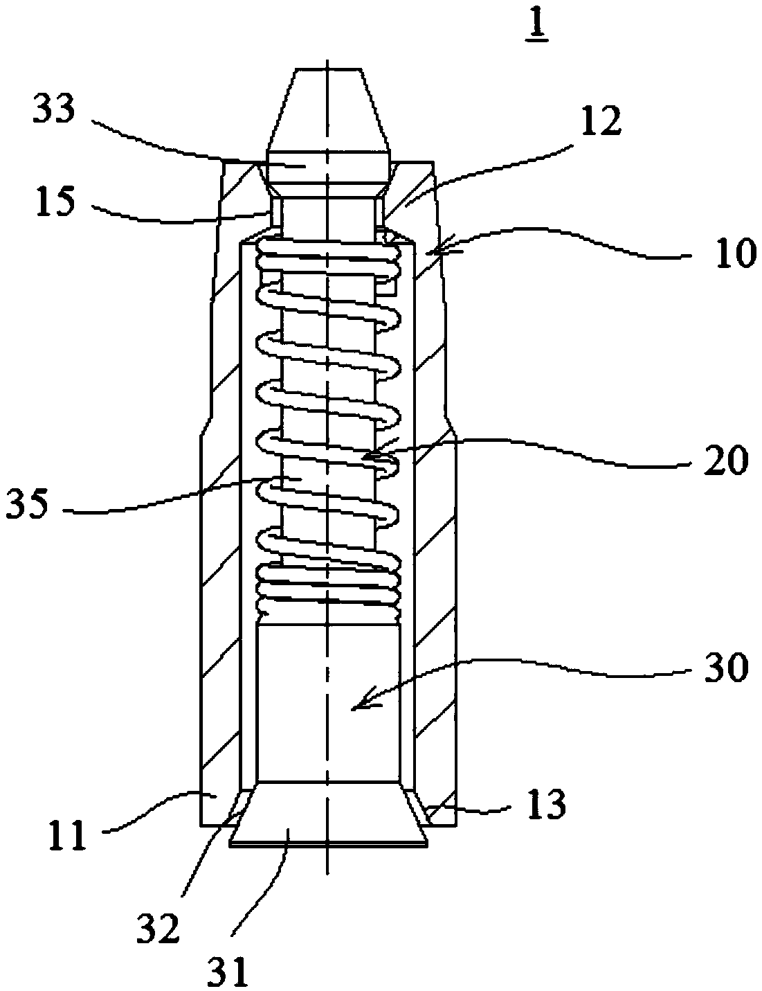
[0042] figure 1 A cross-sectional view of the exhaust device 1 of the present invention is shown. Such as figure 1As shown, to include a casing 10 , a spring 20 and a mandrel 30 , the spring 20 is sleeved on the outer surface of the mandrel 30 and inserted into the casing 10 together with the mandrel 30 .

[0043] The inner peripheral surface of the first end 11 of the outer casing 10 (the end facing the inside of the tire mold in the assembled state) is formed with an outer casing tapered surface 13, and is formed at the second end 12 of the outer casing 10 opposite to the first end 11. There are small hole parts 15 in the jacket.

[0044] A shaft head 31 is formed on an end of the mandrel 30 corresponding to the first end 11 of the casing 10 , and a shaft head cone 32 is formed on an outer peripheral surface of the shaft head 31 . In the assembled state, the mandrel 30 is movable in the outer casing 10 between a first position and a second position, wherein in the first...

no. 2 example

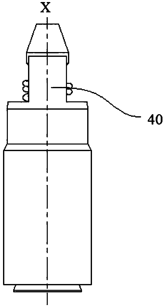
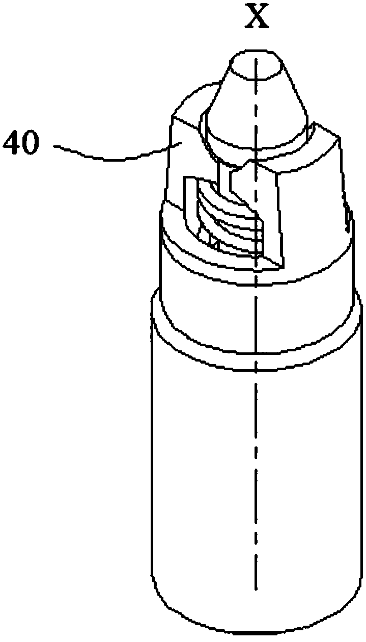
[0067] Figure 6-8 A second embodiment of the invention is shown. Different features between the second embodiment and the first embodiment will be mainly described below. In addition, unless stated to the contrary, the content described in the first embodiment is also applicable to the second embodiment, and will not be described in detail here. Furthermore, in the description of the second embodiment, the same features are given the same reference numerals as those of the first embodiment.

[0068] In the second embodiment, before assembly, the inner diameter of the outer casing small hole portion 15 of the outer casing 10 is set to be slightly larger than the maximum diameter of the small diameter end 33 of the mandrel 30, so that the outer casing small hole portion 15 and the small diameter end 33 can form a clearance fit. Such as Image 6 As shown, there may be a gap σ between the small hole portion 15 of the jacket and the small diameter end 33 , and the size of the ...


PUM


Abstract

The invention discloses an exhaust device. The exhaust device comprises an outer sleeve, a mandrel and a spring, the mandrel is contained in the outer sleeve, the spring sleeves the outer surface of the mandrel, moreover, the spring and the mandrel are inserted into the outer sleeve jointly. An outer sleeve small hole portion is formed at the second end of the outer sleeve, in the assembled state,the inner diameter of the outer sleeve small hole portion is smaller than the maximum diameter of the small-diameter end of the mandrel, so that interference fit is formed between the outer sleeve small hole portion and the small-diameter end, moreover, a milling flat portion is formed at the second end of the outer sleeve, moreover, the outer sleeve small hole portion is exposed, and then at least one clamping jaw is formed. The invention further discloses a tire mold comprising the exhaust device and a method for assembling the exhaust device. According to the exhaust device, disassembly and replacement of the exhaust device can be simplified, and the maintenance cost of the tire mold can be reduced.

Description

technical field [0001] The invention relates to a venting device, in particular for use in tire moulds. The invention also relates to a tire mold with such a venting device. Background technique [0002] In the tire manufacturing process, a green tire is formed in a tire mold, and then the green tire in the mold is vulcanized to form the final tire product. During the vulcanization process, the air in the inner cavity of the tire mold needs to be discharged to prevent air pockets. The method usually used at present is to set vent holes on the tire mold, and the air in the tire mold is directly discharged through the vent holes. [0003] However, there are some problems with this approach, one of which is that in the process of expelling the air out of the tire mold, some of the rubber material used to form the tire is also squeezed out of the vent hole. These extruded rubber materials will form rubber hairs on the tire tread, and the broken rubber hairs will block the ven...

Claims


Application Information

Patent Timeline
Patent Type & Authority Applications(China)
IPC IPC(8): B29C33/10B29C35/02B29L30/00
CPCB29C33/10B29C35/02B29L2030/00
Inventor 李健逄金鹏李宗彪张伟杜平孙日文王万里
Owner GAOMI TONGCHUANG VALVE CORE CO LTD
Why Eureka
Try Eureka