
Barrel Burr Cutting Machine

A cutting machine and burr technology, which is applied in the field of barrel burr processing equipment, can solve the problems of limited adsorption force, easy cutting, easy relative displacement between the barrel body and the leather cup, etc., so as to improve work efficiency, increase the limit degree, Relative Position Reliable Effects

Active Publication Date: 2020-03-24
JIANGSU MINNUO SPECIAL EQUIP CO LTD
View PDF5 Cites 0 Cited by
  • Summary
  • Abstract
  • Description
  • Claims
  • Application Information

AI Technical Summary

Problems solved by technology

[0005] During the use of this deburring machine, a leather cup is used to limit the barrel. The leather cup is an active rotating part, and the adsorption force of the leather cup is limited. It is only driven by the leather cup. When the initial static state changes to a rotating state, At this time, the resistance is the largest. If the barrel body is heavy, when the cup drives the barrel body, the relative displacement between the barrel body and the cup is easy to occur, and when the blade cuts the barrel body, it is easy to cut crookedly.

Method used


Image

  • Barrel Burr Cutting Machine
  • Barrel Burr Cutting Machine
  • Barrel Burr Cutting Machine

Examples


Embodiment 1

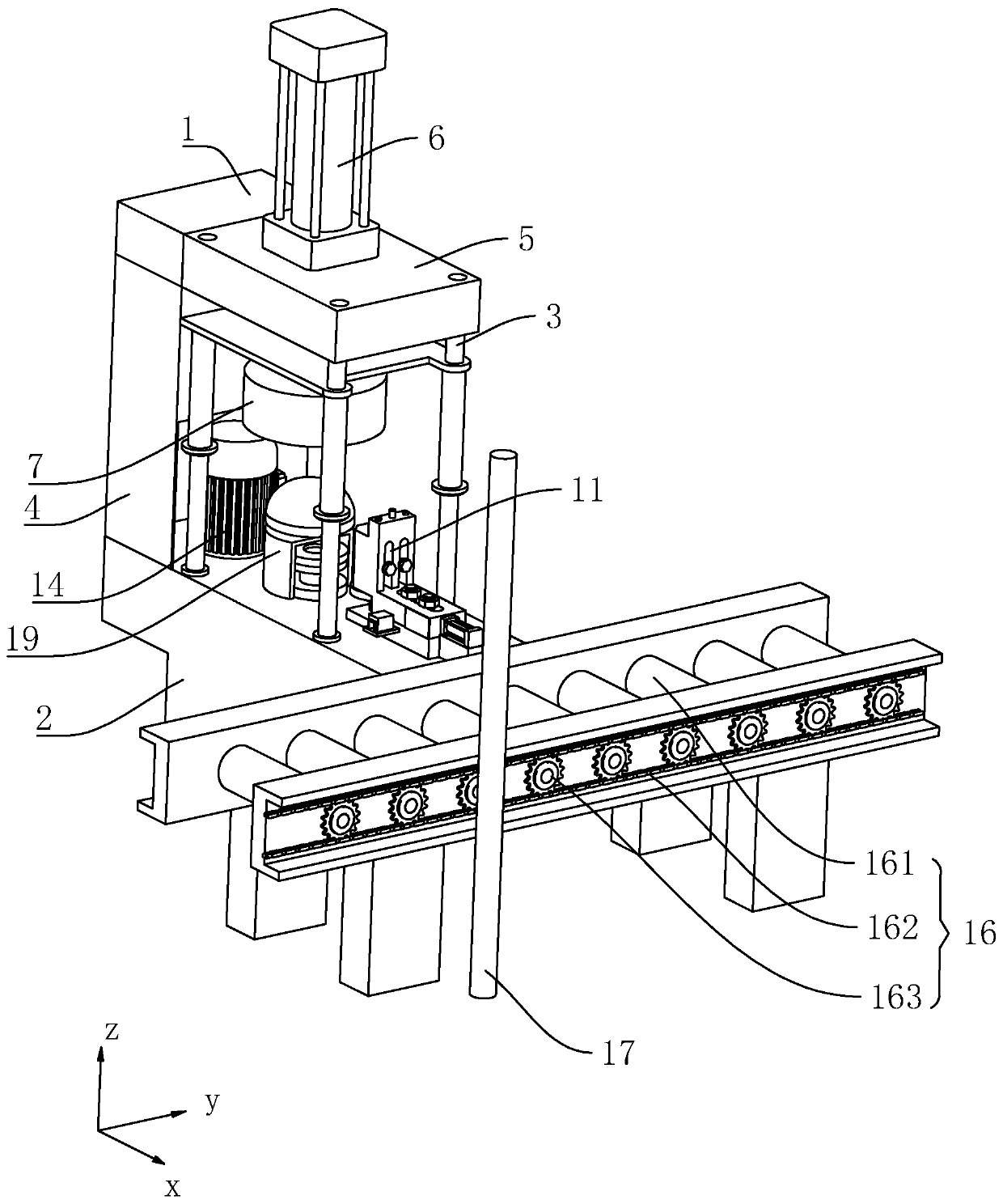
[0038] Embodiment 1: a kind of barrel body flash notch machine, such as figure 2 As shown, it includes a rack 1, and the rack 1 includes a base 2 of a cube, such as figure 2 As shown, a three-dimensional coordinate system is established with the center of the base 2 as the origin, the front of the base 2 is the x direction, the right side of the base 2 in the figure is the y direction, and the top of the base 2 in the figure is the z direction.

[0039] Such as figure 2 As shown, the frame 1 also includes a guide post 3 and a back plate 4, the guide post 3 is vertically arranged at the four corners of the base 2; The sides are drawn vertically upwards, and a top plate 5 is arranged on the top of the back plate 4 , and the projection of the top plate 5 on the z-axis just falls on the base 2 .

[0040] The frame 1 is provided with a part positioning mechanism 19 for limiting the parts to be cut. The part positioning mechanism 19 includes a driving rotating part 20 and a dri...

Embodiment 2

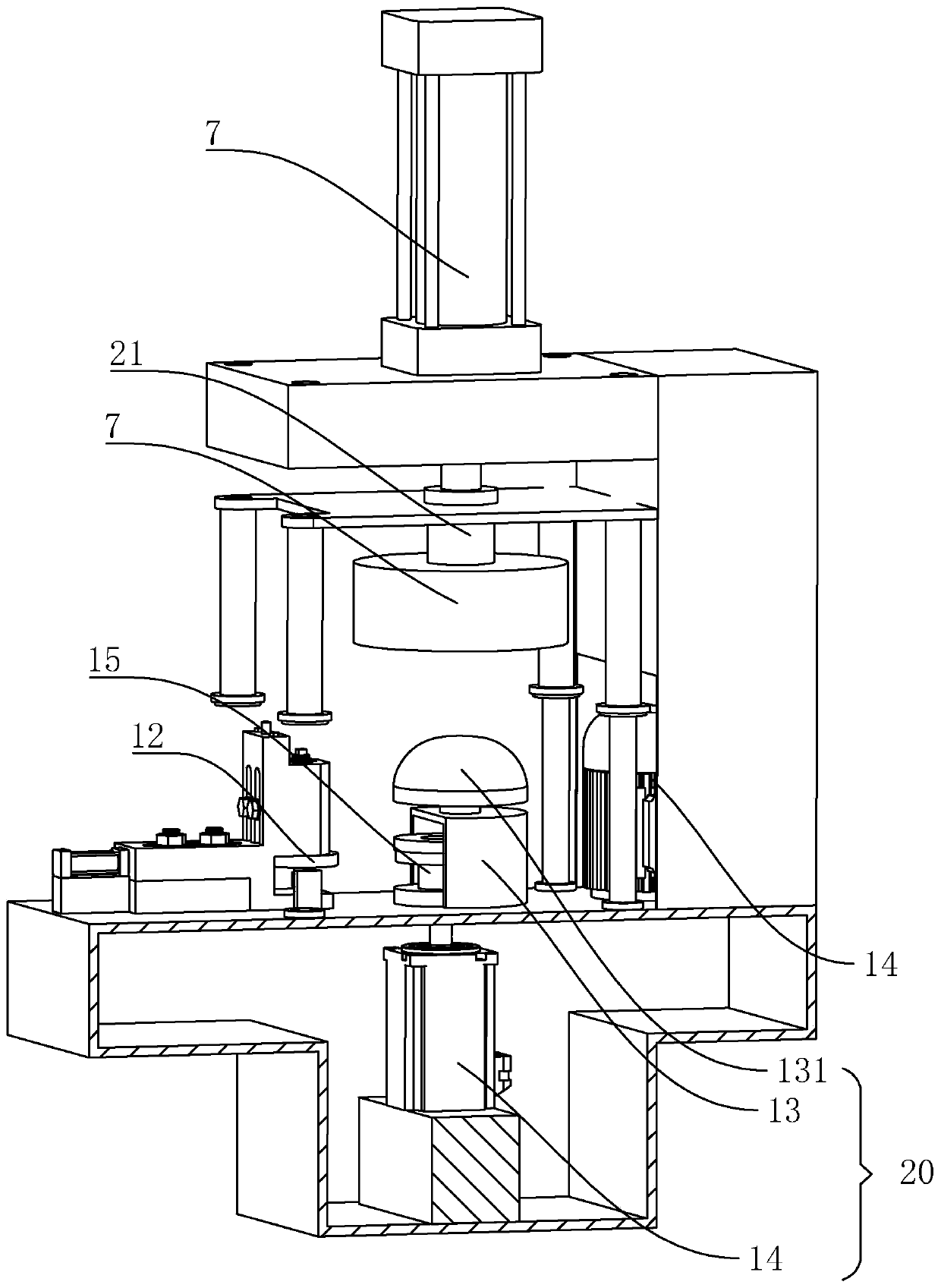
[0055] Embodiment 2: The difference with Embodiment 1 is that, as Figure 5 As shown, there is a transmission connection between the sipe 15 and the geared motor 14 in this embodiment, and a section of the first shaft 132 extends from the bottom of the I-shaped wheel of the sipe 15, and the first shaft 132 is sleeved and tensioned. Belt 18, tension belt 18 other ends are tightened on the output shaft of geared motor 14, and geared motor 14 rotates and drives knife groove 15 to rotate.


PUM


Abstract

The invention belongs to the field of barrel burr treating equipment, and aims to provide a barrel burr cutting machine. The barrel burr cutting machine is characterized in that the barrel burr cutting machine comprises a rack and a tool base; the tool base is located at the side edge of the rack, and the tool base and the rack are relatively slidably connected; a part positioning mechanism is arranged on the rack and comprises a driving rotating piece and a driven pressing piece; the positions of the driving rotating piece and the driven pressing piece in the vertical direction are adjustable; and the face, facing the ground, of the driven pressing piece can generate adsorption force for a to-be-cut part in the using process. By adopting the technical scheme, when the equipment cuts burrsof the to-be-cut part such as a barrel, the driven pressing piece presses the to-be-cut part in the expected position firstly, then the driving rotating piece drives the to-be-cut part to rotate, thus the to-be-cut part simultaneously bears pressing force and the adsorption force from the driven pressing piece in the rotating process, and the relative position relation is limited in the rotatingprocess, so that the to-be-cut part is not prone to slanting cutting.

Description

technical field [0001] The invention relates to the field of processing equipment for barrel burrs, in particular to a barrel burr cutting machine. Background technique [0002] At present, the Chinese patent with the publication number CN203600499U discloses a machine for eliminating burrs on the bottom surface of barrel-shaped products. The rotating motor and the lifting platform are also fixedly connected with a rotating tube. The hollow tube is jacketed with a rotating tube that can produce relative rotary motion with the hollow tube. The hollow tube is also fixed with a rotating wheel, and the rotating wheel is connected to the rotating motor by a belt. The lower end of the hollow tube is connected to the leather cup, and the upper end of the hollow tube is connected to the air pump through a hollow sealed rotary assembly. The rack is provided with a rotating tray below the leather cup, and a bracket is provided on the rack at a position suitable for the rotating tray. ...

Claims


Application Information

Patent Timeline
Patent Type & Authority Patents(China)
IPC IPC(8): B29C37/02
CPCB29C37/02
Inventor 徐太平孔德尧
Owner JIANGSU MINNUO SPECIAL EQUIP CO LTD
Learn More