
Method and system for fast access to advanced visualization of medical scans using a dedicated web portal

a technology of advanced visualization and web portal, applied in image generation, instruments, image enhancement, etc., can solve the problems of large 3d volume dataset, high cost, and impracticality of 3d to be ubiquitous, and achieve the effect of optimizing bandwidth usage, overcoming low bandwidth and high latency limitations, and improving the quality of medical imaging

Active Publication Date: 2020-04-23
AI VISUALIZE INC
View PDF0 Cites 0 Cited by
  • Summary
  • Abstract
  • Description
  • Claims
  • Application Information

AI Technical Summary

Benefits of technology

The present invention aims to provide a solution to overcome the limitations of low bandwidth and high latency in the standard Internet, allowing for optimized bandwidth usage for interactive web applications, such as visualizing large medical scans. It also aims to provide a common and centralized infrastructure for receiving, storing, processing, and viewing large medical scans via a web portal, while maintaining medical records for long periods of time under security and privacy. The technical effects of the invention include improved internet connectivity for medical scans and other medical datasets, and a more efficient and secure way of managing and viewing large medical scans.

Problems solved by technology

However, the current solutions are impractical for 3D to be ubiquitous.
Computed Axial Tomography (CT) scans or magnetic resonance imaging (MRI) scans of a patient's body results in large 3D volume datasets that are time consuming when transported over the Internet.
This becomes expensive and adds an administrative burden that only a select few provide such a “luxurious” functionality to their physicians.
Internet access via web portal particularly low bandwidth and high latency situation of rural area can hinder the user interactivity of information presented in 3D.
Latency, i.e., delay in the time it takes for a packet of data to travel from one designated point to another in response to a request, is particularly problematic for users having low bandwidth Internet communication.
For large 3D, four-dimensional (4D), or higher dimensional scans, the retrieving or raw scan for processing is impractical or impossible over low bandwidth network.
However, such technique requires sufficient bandwidth and low latency network to present information at interactive frame rates.
This presents a problem for rural areas to gain access to medical scans in advanced visualization format interactively.
This becomes expensive and adds a management burden to facilities as there can be IT, physical space and cost administration limitations.

Method used


Image

  • Method and system for fast access to advanced visualization of medical scans using a dedicated web portal
  • Method and system for fast access to advanced visualization of medical scans using a dedicated web portal
  • Method and system for fast access to advanced visualization of medical scans using a dedicated web portal

Examples


Embodiment Construction

)

[0034]In describing the preferred embodiment of the present invention, reference will be made herein to FIGS. 1-5 of the drawings in which like numerals refer to like features of the invention.

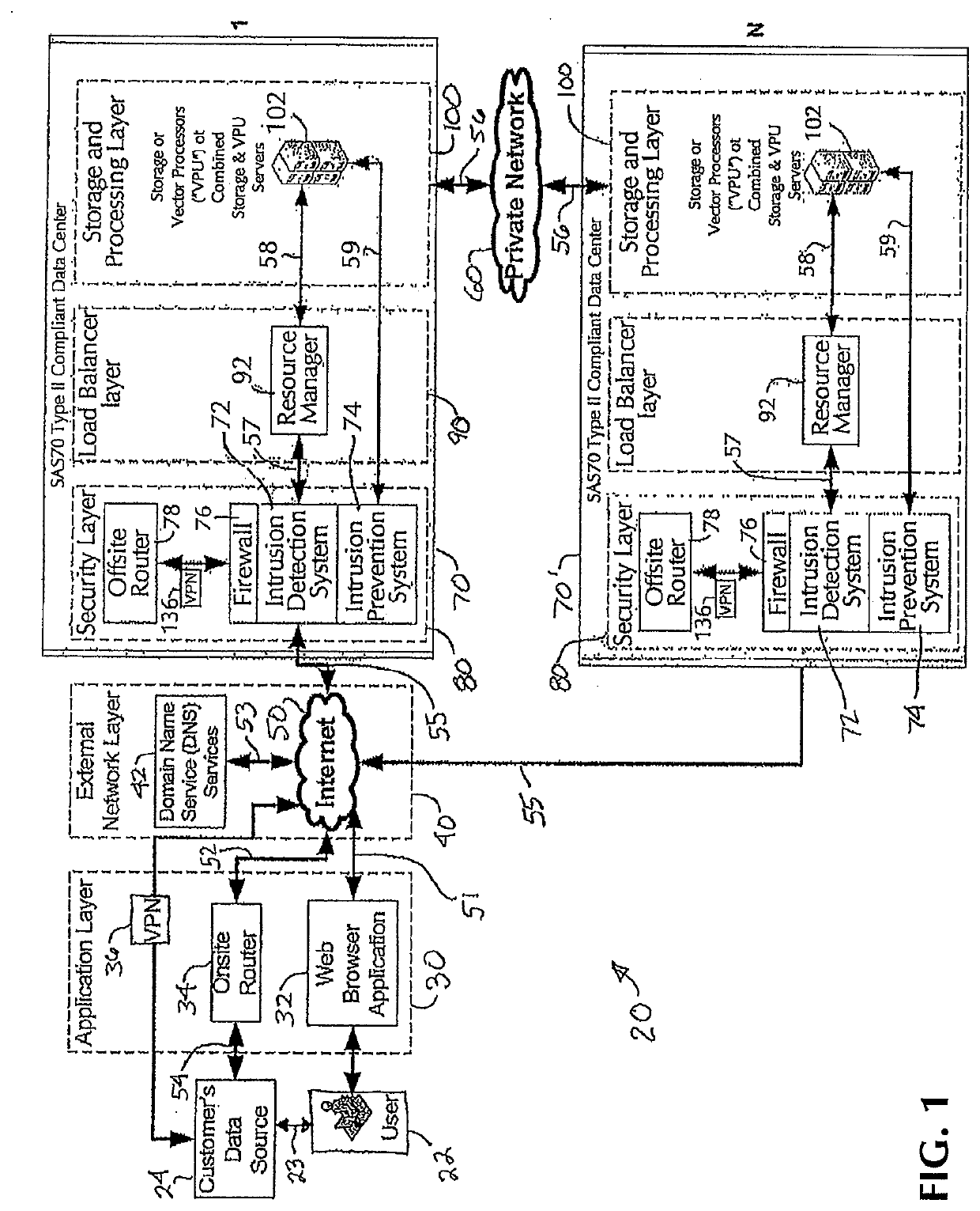
[0035]The present invention in one embodiment provides a method and system for fast access to advanced visualization of medical scans using a dedicated web portal, in particular, advanced visualization of volumetric data, for example, medical scans. As shown in FIG. 1, one embodiment of the method and system 20 of the present invention consists of a number of functional components or layers, i.e., Application Layer 30, External Network Layer 40, Security Layer 80, Load Balancer Layer 90, and Storage and Processing Layer 100. Communication and transmission connections between the individual system components or layer, as well as with the server and users, may be made by wireless, wireline, optical fiber cable, radio frequency (RF) or the like, and may also be made via an internal network (LAN)...


PUM


Abstract

A system for viewing at a client device a series of three-dimensional virtual views over the Internet of a volume visualization dataset contained on centralized databases employs a transmitter for securely sending volume visualization dataset from a remote location to the centralized database, more than one central data storage medium containing the volume visualization dataset, and a plurality of servers in communication with the centralized databases to create virtual views based on client requests. A resource manager load balances the servers, a security device controls communications between the client device and server and the resource manager and central storage medium. Physically secured sites house the components. A web application accepts at the remote location user requests for a virtual view of the volume visualization dataset, transmits the request to the servers, receives the resulting virtual view from the servers, and displays the resulting virtual view to the remote user.

Description

RELATED APPLICATIONS[0001]This application is a continuation of U.S. patent application Ser. No. 16 / 116,524 filed Aug. 29, 2018, which is a continuation of U.S. patent application Ser. No. 15 / 817,785 filed Aug. 21, 2017, now U.S. Pat. No. 10,084,846, which is a continuation of U.S. patent application Ser. No. 15 / 255,775 filed Sep. 2, 2016, now U.S. Pat. No. 9,749,389, which is a continuation of U.S. patent application Ser. No. 14 / 754,953 filed Jun. 30, 2015, now U.S. Pat. No. 9,438,667, which is a continuation of U.S. patent application Ser. No. 14 / 187,996 filed Feb. 24, 2014, now U.S. Pat. No. 9,106,609, which claims priority from U.S. patent application Ser. No. 14 / 322,359 filed Nov. 23, 2011, now U.S. Pat. No. 8,701,167, which is a National Stage Application of PCT / US2010 / 036355 filed May 27, 2010, which claims priority from U.S. provisional application No. 61 / 181,695, filed on May 28, 2009.BACKGROUND OF THE INVENTION1. Field of the Invention[0002]This invention relates to a meth...

Claims


Application Information

Patent Timeline
Patent Type & Authority Applications(United States)
IPC IPC(8): G16H50/20G06T7/00H04L9/32G16H30/20
CPCG06T2210/41G06T2207/10072H04L9/32G06T7/0012G16H50/20G16H30/20G16H40/20G16H40/67H04L67/12H04L63/0428
Inventor KOVALAN, KOVEY
Owner AI VISUALIZE INC
Learn More