A Piezoelectric Inkjet Printing Nozzle Structure to Prevent Ink Backflow

An inkjet printing and nozzle technology, applied in the field of piezoelectric inkjet printing nozzle structure to prevent ink backflow, can solve the problems of increasing the cost of ink cartridges, achieve the effects of improving inkjet efficiency, good ink backflow prevention, and low preparation cost

Active Publication Date: 2019-07-09
大连瑞林数字印刷技术有限公司
View PDF6 Cites 0 Cited by
  • Summary
  • Abstract
  • Description
  • Claims
  • Application Information

AI Technical Summary

Problems solved by technology

Thermal inkjet printers require nozzles to be installed in each cartridge: this increases the cost of the cartridge

Method used


Image

  • A Piezoelectric Inkjet Printing Nozzle Structure to Prevent Ink Backflow
  • A Piezoelectric Inkjet Printing Nozzle Structure to Prevent Ink Backflow
  • A Piezoelectric Inkjet Printing Nozzle Structure to Prevent Ink Backflow

Examples


Embodiment 1

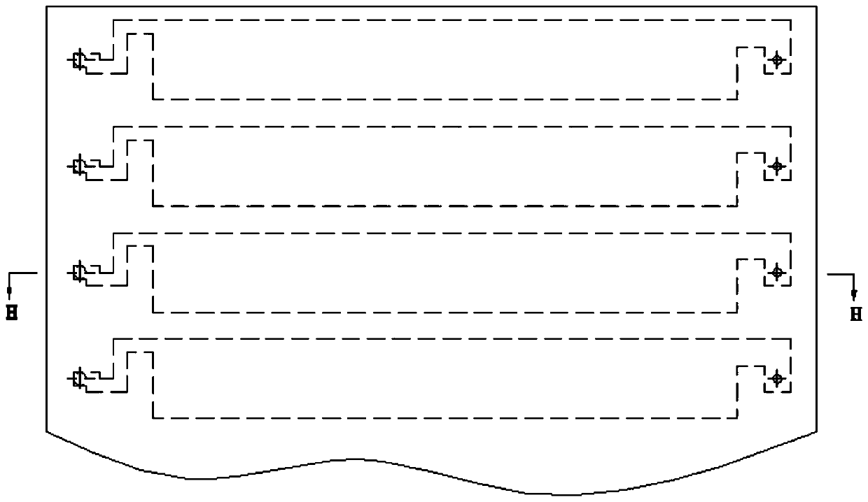
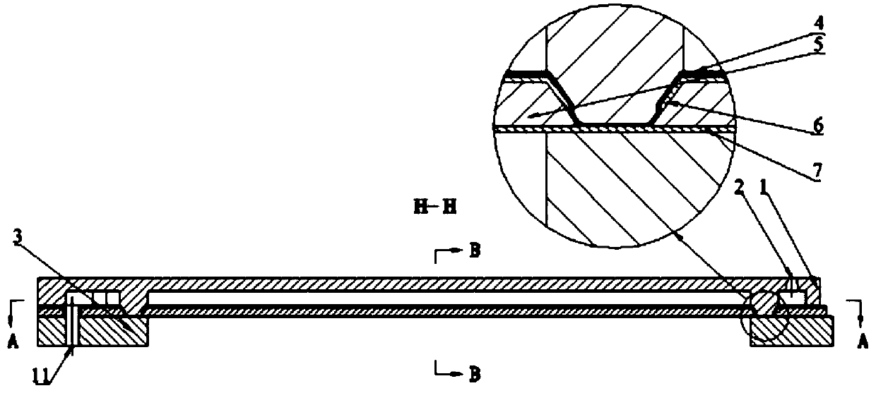
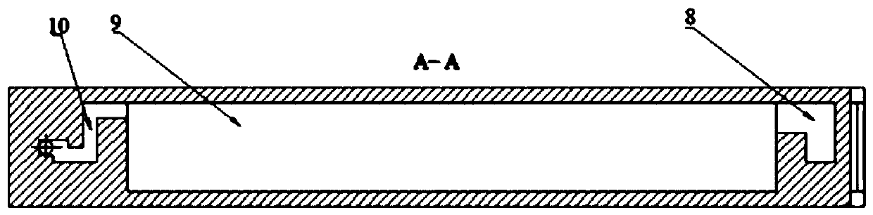
[0062] Such as figure 1 As shown, a piezoelectric inkjet printing head for preventing ink backflow in this embodiment includes a plurality of chambers, such as Figure 2a As shown in -c, each chamber includes: an ink supply channel 11 , a restrictor 10 , a pressure generating chamber 9 , a drain 8 , a nozzle 2 , an upper electrode 6 , a piezoelectric ceramic 5 , a lower electrode 7 , and a vibrating plate 4 .

[0063] Such as image 3 As shown, the structural size of the restrictor in this design is: the length of side a is 50um, the length of side b is 150um, the length of side c is 25um, the length of side d is 50um, the length of side e is 150um, and the length of side f is 150um. The length of side g is 150um, the length of side g is 50um, the length of side h is 100um, the length of side i is 150um, the length of side j is 150um, the length of side k is 25um, and the length of side l is 100um, such as Image 6 As shown, the height of the pressure generating chamber, the...


PUM


Abstract

The invention provides a piezoelectric inkjet printing spray head structure preventing ink backflow. An ink supply channel is connected with an ink box. Due to capillary force action, the ink supply channel, a flow limiting part, a pressure generation cavity and a flow guide part are full of ink sequentially, and the ink reaches a nozzle. An upper electrode, piezoelectric ceramics, a lower electrode and a vibration plate form a driving element, when the upper electrode and the lower electrode are electrified simultaneously, the piezoelectric ceramics deform due to an inverse piezoelectric effect, then the vibration plate is driven to deform, the vibration plate deforms to extrude the ink in the pressure generation cavity, the flow limiting part and the flow guide part prevent the ink fromflowing back to the ink supply channel, and the ink is sprayed out from the nozzle. The piezoelectric ceramics are used for the piezoelectric inkjet printing spray head structure, the driving elementgenerate driving force, removing machining is conducted on the base part corresponding to the pressure generation cavity, and the driving element is in a suspension state and is located in the e pressure generation cavity. The piezoelectric inkjet printing spray head structure is simple in manufacture process, low in cost and good in process repeatability and has an ink backflow prevention effect.

Description

technical field [0001] The present invention relates to include ink cartridge, ink supply channel, restrictor, pressure generating cavity, drainage part, nozzle, upper electrode, piezoelectric ceramics, lower electrode, vibrating plate, particularly, the present invention relates to the pressure that ejects liquid from nozzle place Electro-ink jet printing jet head. Background technique [0002] Inkjet printers turn colored liquid ink into fine particles through nozzles and spray them onto printing paper. Some inkjet printers have three or four printing nozzles to print four colors of yellow, magenta, cyan and black; Four-color printing. There are two main technologies used in inkjet printers: continuous inkjet technology and random inkjet technology. [0003] Early inkjet printers and current large-format inkjet printers all use continuous inkjet technology, while the current popular inkjet printers generally use random inkjet technology. The continuous inkjet technology...

Claims


Application Information

Patent Timeline
Patent Type & Authority Patents(China)
IPC IPC(8): B41J2/14
CPCB41J2/14201
Inventor 韩梅
Owner 大连瑞林数字印刷技术有限公司
Why Eureka
Try Eureka