Gradient adjusting steering column
A steering column and gradient adjustment technology, applied in the steering column, steering control, steering mechanism, etc., can solve the problems of inability to automatically return, the steering column angle adjustment range is fixed, and the control adjustment is inconvenient, and the adjustment range is small. , Reduce the difficulty of operation and ensure the effect of locking retention
- Summary
- Abstract
- Description
- Claims
- Application Information
AI Technical Summary
Problems solved by technology
Method used
Image
Examples
Embodiment 1
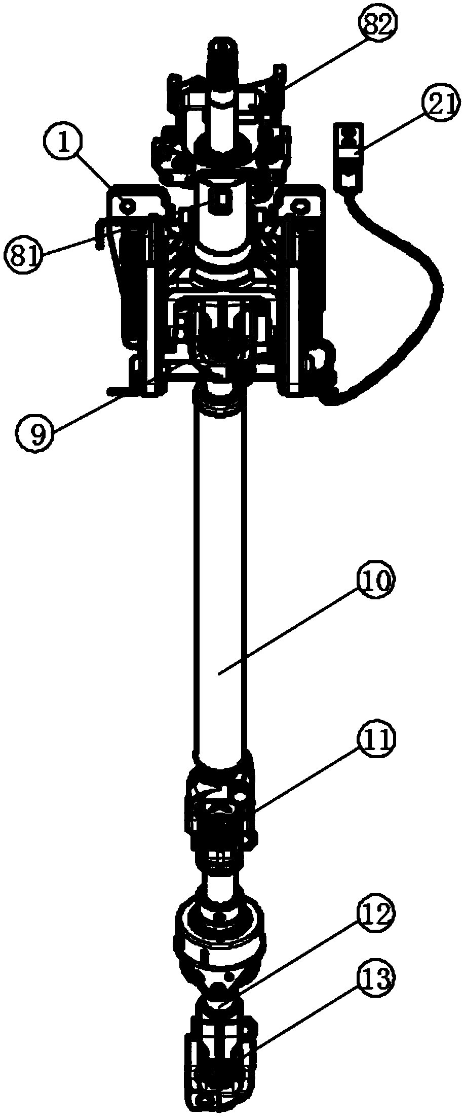
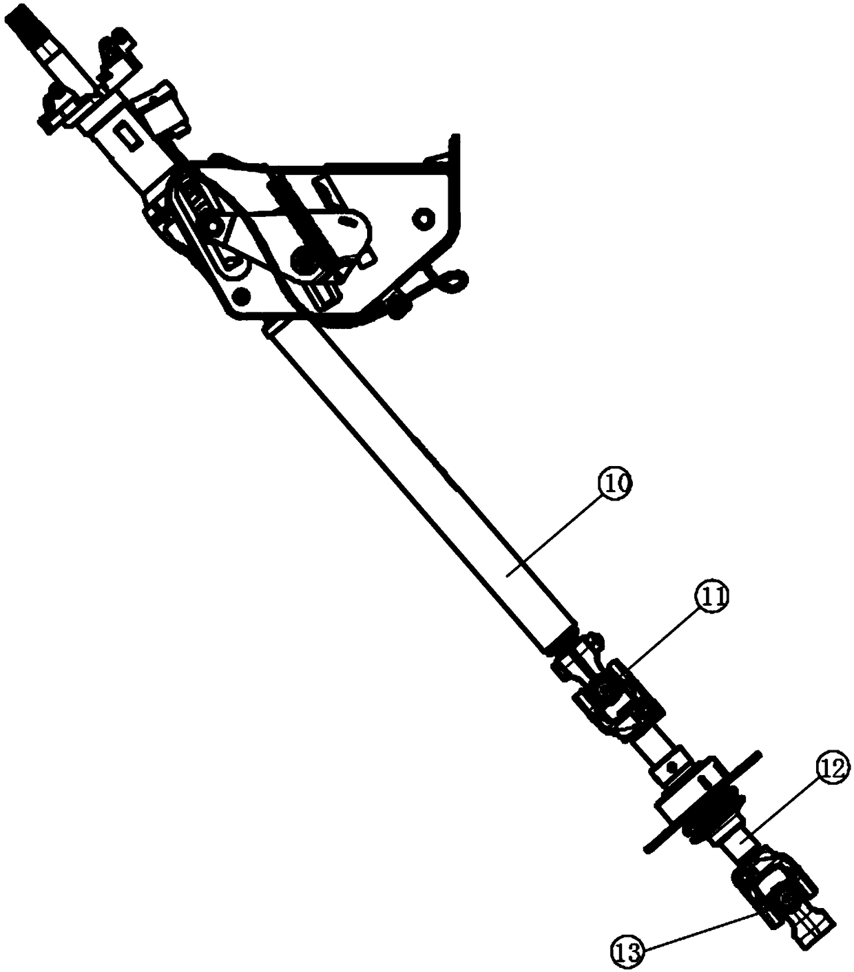
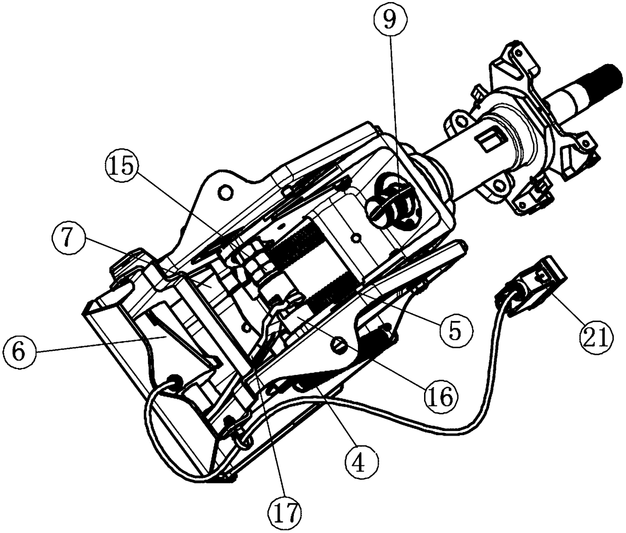
[0039] Such as figure 1 with figure 2 As shown, this embodiment provides a gradient adjustable steering column. The top of the steering column is connected to the steering wheel through the steering shaft, and the bottom of the steering column is connected to the ball telescopic bushing assembly 10 through the constant velocity universal joint assembly 9 . The ball telescopic bushing assembly 10 is connected to the intermediate shaft 12 through the universal joint assembly 11, the intermediate shaft 12 is connected to the lower universal joint assembly 13 through bolts, the lower universal joint assembly 13 is connected to the steering gear, and the column tube 8 An ignition lock hole 81 and a flange 82 are arranged on the top, the ignition lock hole 81 is connected with the automobile ignition lock, and the flange 82 is connected with a combination switch, a sensor, and a clock spring.
[0040] When the driver turns the steering wheel, the steering wheel drives the steering...
Embodiment 2
[0046] Such as Figure 4 with Figure 5 As shown, this embodiment is further optimized on the basis of Embodiment 1, specifically including a pneumatic delay valve 21, the output end of the pneumatic delay valve 21 is connected to the cylinder 6, and the input end of the pneumatic delay valve 21 is connected to the automobile Air connection.
[0047] The principle of use of the pneumatic delay valve 21: when the driver touches the unlocking button of the pneumatic delay valve 21, the air source of the vehicle will quickly enter the interior of the one-way valve cavity, and the air pressure pushes the inner copper rod valve sleeve. After the spring is compressed, the gas directly Through the air outlet pipe, it directly flows into the booster cylinder 6 at the tail end, pushes the spring to compress, the piston of the cylinder 6 is retracted and unlocked successfully, and the adjustment mechanism can be adjusted freely. After unlocking for a certain period of time, the air va...
Embodiment 3
[0049] Such as Figure 7 , Figure 8 with Figure 12 As shown, this embodiment is further optimized on the basis of Embodiment 2. Specifically, the initial angle between the center line of the column tube 8 and the horizontal plane is 50 degrees, the central angle corresponding to the arc-shaped through groove is 35 degrees, and the long bolt 14 The initial position is located in the middle of the arc-shaped through groove, the length of the chute 18 is 70 cm, and the bottom surface of the contour limiting plate 19 is curved.
[0050] Set the angle between the center line of the column tube 8 and the ground plane to 50 degrees, that is, set the reference man-machine angle to 50 degrees, compared with the 75-80 degrees used in batches of domestic automobile column assemblies and the 65-80 degrees of some commercial vehicles. 70, can reduce the angle between the driver's body and the ground plane, make the driver's reclining angle larger, closer to "lying down" driving, improv...
PUM
 Abstract
Description
Claims
Application Information
 - R&D
- Intellectual Property
- Life Sciences
- Materials
- Tech Scout
- Unparalleled Data Quality
- Higher Quality Content
- 60% Fewer Hallucinations
Browse by: Latest US Patents, China's latest patents, Technical Efficacy Thesaurus, Application Domain, Technology Topic, Popular Technical Reports.
© 2025 PatSnap. All rights reserved.Legal|Privacy policy|Modern Slavery Act Transparency Statement|Sitemap|About US| Contact US: help@patsnap.com


