
Valve feeding device

A valve and equipment technology, applied in the field of valve feeding equipment, can solve the problems of limited worker fatigue, low work efficiency, unfavorable valve mass production, etc., and achieve the effect of improving the overall processing efficiency

Inactive Publication Date: 2018-11-06
ANHUI WODE VALVE MFG
View PDF13 Cites 8 Cited by
  • Summary
  • Abstract
  • Description
  • Claims
  • Application Information

AI Technical Summary

Problems solved by technology

[0002] Automobile valves are mainly used to start and close the intake port and exhaust port during the working process of the engine to control the entry of fuel mixture or air and the discharge of exhaust gas. In actual production, there are high requirements for the processing of the valve. Now the valves in the factory are processed in an assembly line. After some processing procedures are completed, more valves are piled up in a disorderly manner. When the next process is carried out, the disordered valves need to be sorted. In the prior art, workers sort them manually. After sorting, the material is loaded through the transmission mechanism. Manual sorting has disadvantages such as low work efficiency and limited worker fatigue, which is not conducive to mass production of valves.

Method used


Image

  • Valve feeding device
  • Valve feeding device
  • Valve feeding device

Examples


Embodiment Construction

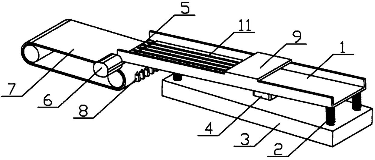
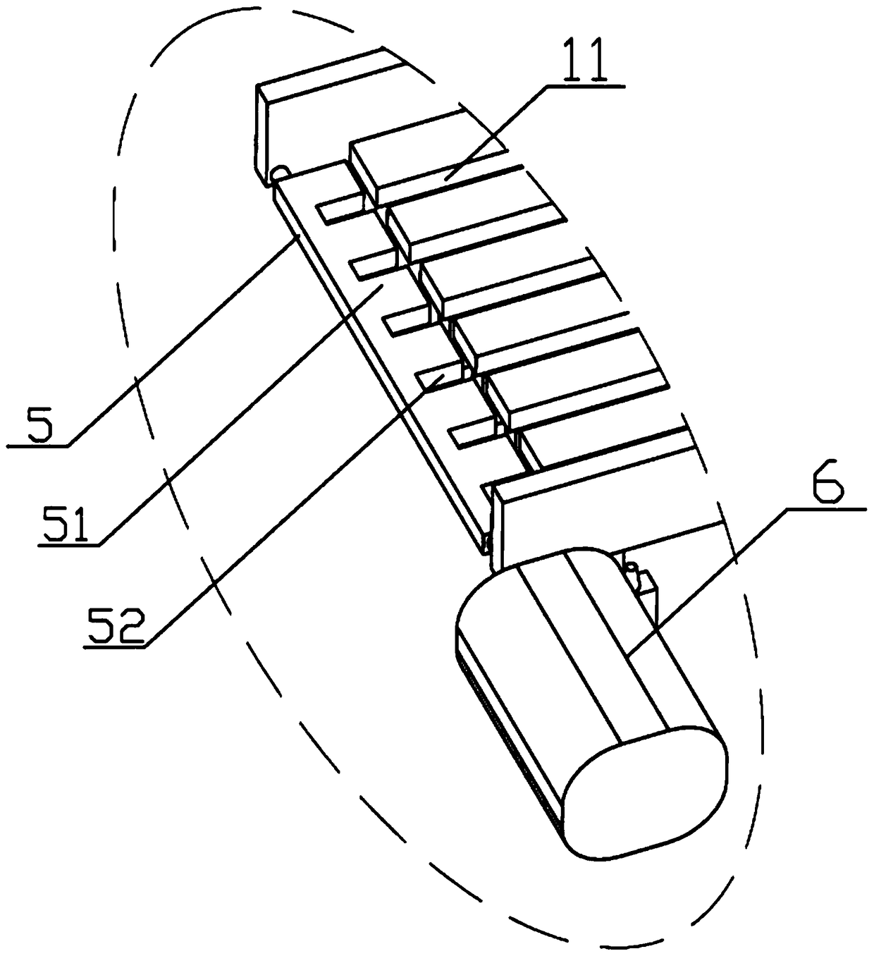
[0017] like Figure 1-4 as shown, figure 1 It is an axonometric view of a valve feeding device proposed by the present invention, figure 2 It is a side view of a valve feeding device proposed by the present invention, image 3 It is a partially enlarged view of a valve feeding device proposed by the present invention, Figure 4 It is a schematic diagram of the working process of a valve feeding device proposed by the present invention.

[0018] refer to Figure 1-2 , a valve feeding device proposed by the present invention, comprising a transmission plate 1, an elastic element 2, a base 3, a vibrator 4, a stop rod 5, a servo motor 6 and a belt conveyor 7;

[0019] The transmission plate 1 has a rectangular plate structure, and the transmission plate 1 is installed above the base 3 through the elastic element 2. The elastic element 2 in this embodiment is four springs, and the four springs are located between the transmission plate 1 and the base 3. The two ends are respe...


PUM


Abstract

The invention discloses a valve feeding device. A conveying plate is mounted on a base by an elastic member, and the conveying plate is arranged obliquely. A vibrator is used for driving the vibrationof the conveying plate, and the conveying plate is provided with a plurality of slides. The multiple slides extend to the discharging end in the conveying direction of the conveying plate, and the slides are used for accommodating the stem portions of valves. A blocking rod is positioned in the extending direction of the conveying surface of the conveying plate, and a plurality of receiving grooves are formed in the blocking rod. The multiple receiving grooves and the multiple slides are in one-to-one correspondence for receiving the valves which slide down through the slides, and a servo motor is used for driving the rotation of the blocking rod. The valves in the receiving grooves are driven to a belt conveyor under the rotation state of the blocking rod. According to the valve feedingdevice, the conveying plate has two functions of conveying the valves to a next process and sorting the valves in the conveying process, so that the disordered valves are sorted by the conveying plateto form a regular arrangement, the processing of the valves in the following process is facilitated, and the overall processing efficiency of the valves is improved.

Description

technical field [0001] The invention relates to the technical field of valve processing equipment, in particular to a valve feeding equipment. Background technique [0002] Automobile valves are mainly used to start and close the intake port and exhaust port during the working process of the engine to control the entry of fuel mixture or air and the discharge of exhaust gas. In actual production, there are high requirements for the processing of the valve. Now the valves in the factory are processed on the assembly line. After some processing procedures are completed, more valves are piled up in a disorderly manner. When the next process is carried out, the disordered valves need to be sorted. In the prior art, workers sort them manually. , After sorting, the material is loaded through the transmission mechanism. Manual sorting has disadvantages such as low work efficiency and limited worker fatigue, which is not conducive to mass production of valves. Contents of the inve...

Claims


Application Information

Patent Timeline
IPC IPC(8): B65G47/14B65G47/26B65G47/74
CPCB65G47/14B65G47/26B65G47/74B65G2201/0214
Inventor 林青锋
Owner ANHUI WODE VALVE MFG
Learn More