Road pavement marking method on basis of road pavement guide line marking device

A technology for road markings and guide lines, applied in roads, roads, road repairs, etc., can solve the problems of reduced labor efficiency, complicated procedures, and single functions, so as to reduce manual labor, improve marking effects, and improve marking The effect of line efficiency

Active Publication Date: 2018-11-06
山西永泰峰达建设工程有限公司
View PDF7 Cites 4 Cited by
  • Summary
  • Abstract
  • Description
  • Claims
  • Application Information

AI Technical Summary

Problems solved by technology

This application has a single function, and can only realize marking and drying the marking. However, the road needs to be cleaned before the marking, but the marking device currently used does not have the function of cleaning the road, which makes it necessary to clean the road. Manual cleaning reduces labor efficiency and increases labor workload. At the same time, the existing marking devices use diesel or gasoline to generate electricity, which is not conducive to sustainable development. The existing marking devices have the same marking width , Insufficient flexibility, affecting the normal road marking arrangement, resulting in cumbersome marking work. At the same time, the raw material storage barrel used in the existing marking device does not have a heating function, and it is easy to cool and solidify the raw material during use, which affects the use effect, and when re-doing the guide line for the existing damaged guide line, the process is complicated, the labor force used is large, time-consuming and labor-intensive, for this reason, we propose a highway pavement marking device based on the road surface guide line marking device method

Method used


Image

  • Road pavement marking method on basis of road pavement guide line marking device
  • Road pavement marking method on basis of road pavement guide line marking device
  • Road pavement marking method on basis of road pavement guide line marking device

Examples


Embodiment Construction

[0028]The following will clearly and completely describe the technical solutions in the embodiments of the present invention with reference to the accompanying drawings in the embodiments of the present invention. Obviously, the described embodiments are only some, not all, embodiments of the present invention.

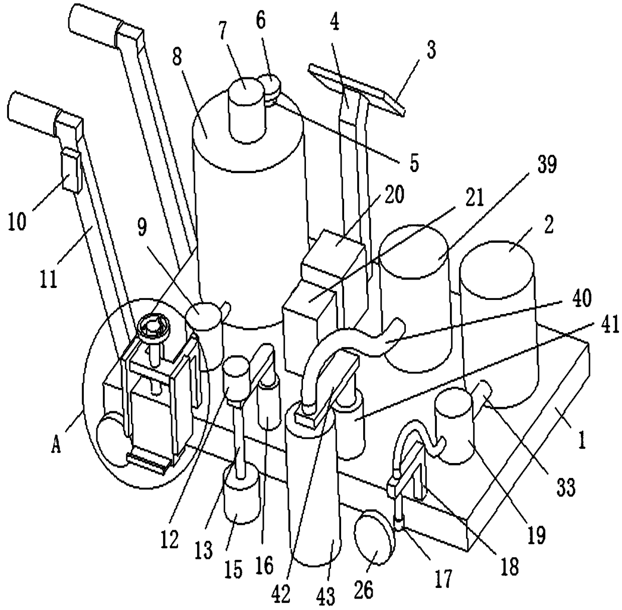
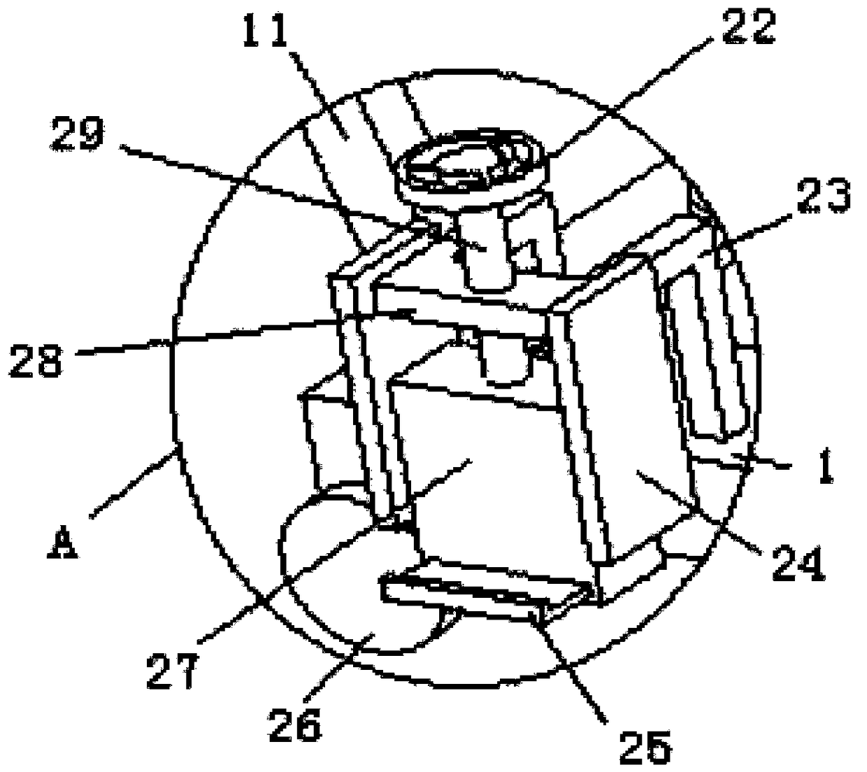
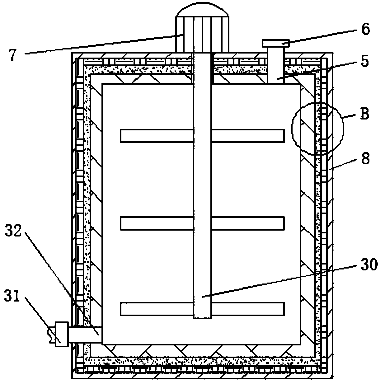
[0029] refer to Figure 1-7 , a highway pavement marking method based on a highway pavement guide line marking device, said method comprising the steps of:

[0030] (1) Adjust the distance between the two pull-out baffles (25) according to the width of the desired marking line, and turn the turntable (22) at the same time to make the threaded rod (29) move through the ball (34) The plate (27) moves, and the moving plate (27) drives the spray gun (35) to move, adjust to a suitable height, and move the marking device to the road surface to be marked;

[0031] (2) Control the first electric telescopic rod (16) through the control panel (10) to make the cleaning brush (1...


PUM


Abstract

The invention relates to the technical field of road pavement marking, in particular to a road pavement marking method on the basis of a road pavement guide line marking device. The road pavement guide line marking device comprises a bottom plate. A storage shell is arranged on a side of the upper end of the bottom plate, a ball is connected with the lower end of a threaded rod, a movable plate isconnected with the outer side of the ball by a ball groove, the end, which is far away from a first pump, of a discharge pipe penetrates a through hole and is connected with a spray gun, and withdrawal barriers are inserted in two sides of the movable plate. The road pavement marking method has the advantages that to-be-marked pavements can be swept by a sweeping brush, accordingly, marking effects can be improved, manual sweeping can be omitted, and the work efficiency can be improved; the to-be-marked pavements can be washed by a spray nozzle, accordingly, sticky objects can be brushed awayby the sweeping brush, and the marking effects can be improved; the storage shell has a heating function, and accordingly raw materials can be prevented from being cooled and solidified in long-timeuse; original guide lines can be cleared, the road pavement guide line marking device is simple in structure and convenient to use, energy can be saved, the amount of hand labor can be reduced, and the marking efficiency can be improved.

Description

technical field [0001] The invention relates to the technical field of highway pavement marking, in particular to a highway pavement marking method based on a highway pavement guide line marking device. Background technique [0002] With the continuous increase of our country's comprehensive strength, the mileage of our country's highways continues to increase. Among them, people usually mark traffic markings on the road surface. Traffic marking refers to the use of lines, arrows, characters, facades Signs, protruding road signs and outline signs, etc., convey traffic information such as guidance, restrictions, and warnings to traffic participants. Their function is to control and guide traffic. They can be used in conjunction with signs or alone. [0003] Chinese patent CN 205420991 U discloses a road surface marking device, which includes a frame, two handles are welded to the front end of the frame, a main pulley is fixed on the output shaft of the gasoline engine, and a ...

Claims


Application Information

Patent Timeline
Patent Type & Authority Applications(China)
IPC IPC(8): E01C23/22
CPCE01C23/22
Inventor 王小玲里科夫斯基
Owner 山西永泰峰达建设工程有限公司
Why Eureka
Try Eureka