Method and device for controlling deformation of soil around foundation pit

A deformation control and foundation pit technology, which is applied in soil protection, excavation, infrastructure engineering, etc., can solve the problems of disturbed soil, waste, and increased cement slurry pouring amount, so as to avoid disturbance, waste and environmental pollution. , Compensate the effect of surrounding soil deformation

Active Publication Date: 2020-10-30
上海勘察设计研究院(集团)股份有限公司
View PDF4 Cites 0 Cited by
  • Summary
  • Abstract
  • Description
  • Claims
  • Application Information

AI Technical Summary

Problems solved by technology

This process usually cannot control the flow direction of cement slurry, which can lead to several problems:
[0003] 1. Cement grout only fills the gaps between soil bodies, and cannot effectively compensate for the deformation of surrounding buildings and tunnels caused by foundation pit excavation
[0004] 2. The dispersion of cement grout will disturb the soil to a certain extent, destroy the soil structure, and may further increase the deformation of the protected object before the grout solidifies
[0005] 3. The injected cement slurry only strengthens the soil, but does not form an effective and concentrated reinforcement, which cannot effectively control the further development of deformation
[0006] 4. After the grouting pipe is filled with cement slurry, it can only be used once due to the cement solidification and plugging, and cannot be used for secondary or multiple grouting, nor can it be segmented
[0007] 5. Due to the inability to control the flow direction of cement slurry, the amount of cement slurry poured increases, causing waste and polluting the environment
[0008] In addition, general grouting measures do not pay attention to the monitoring data of protected objects, and often grouting based on experience, and do not adjust parameters such as grouting volume, grouting pressure, and grouting speed based on monitoring feedback data
[0009] To sum up, the existing technology cannot effectively restore the environmental deformation around the foundation pit, but will further disturb the soil, increase the deformation, and cannot effectively control the further development of the deformation. At the same time, it cannot solve the problem of multiple grouting and environmental problems. Pollution, grouting parameters based on experience, etc.

Method used


Image

  • Method and device for controlling deformation of soil around foundation pit
  • Method and device for controlling deformation of soil around foundation pit
  • Method and device for controlling deformation of soil around foundation pit

Examples


Embodiment 1

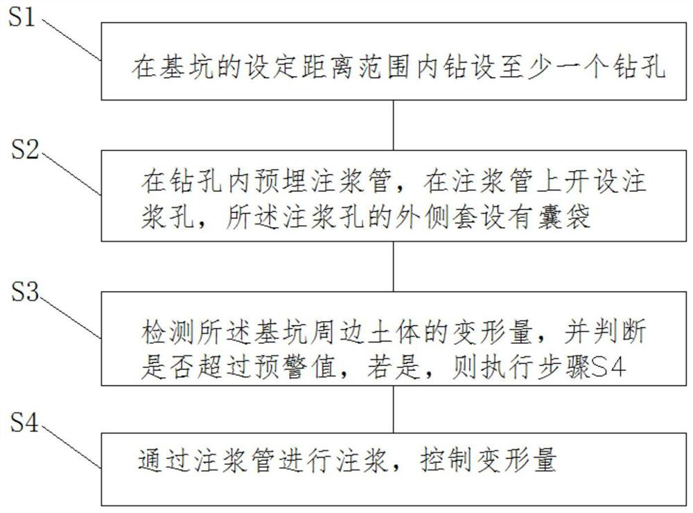
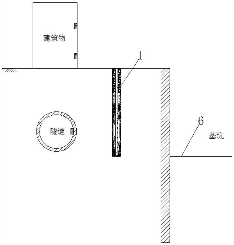
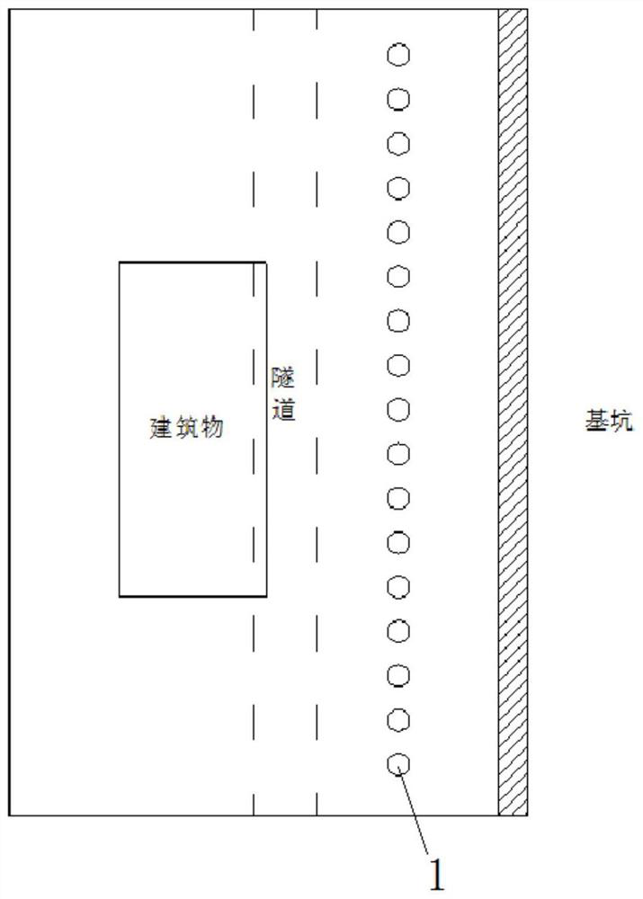
[0090] refer to Figure 2-5 As shown, the specific implementation steps are as follows:

[0091] 1) Locate the pre-embedded position of the grouting pipe 7. The pre-embedded distance of the grouting pipe 7 is 6m from the tunnel, and the pre-embedded distance between adjacent grouting pipes 7 is 3m. A geological drilling rig is used to construct a pre-drilled hole 1. The diameter of the drilled hole 1 is 110mm. The drilling depth is 3m greater than the buried depth at the bottom of the tunnel;

[0092] 2) The grouting pipe 7 is made of DN25 galvanized steel pipe, and holes are made on the grouting pipe 7 where grouting is required. The diameter of the holes is 5mm, and the distance between the holes is 0.1m. The pouch 5 has a length of 12m;

[0093] 3) Lower the grouting pipe 7 to the pre-drilled hole 1, fill sand outside the grouting section to form a sand-filling section 2, and perform grouting plugging above the sand-filling section 2, and the grouting water-cement ratio i...

Embodiment 2

[0098] refer to Figure 6-7 As shown, the specific implementation steps are as follows:

[0099] 1) Locate the pre-embedded position of the grouting pipe 7. The pre-embedded distance of the grouting pipe 7 is 6m from the building, and the pre-embedded distance between adjacent grouting pipes 7 is 3m. Use a geological drilling rig to construct the pre-drilled hole 1, the diameter of the drilled hole 1 110mm, the drilling depth is 8m greater than the buried depth of the building foundation;

[0100] 2) The grouting pipe 7 is made of DN25 galvanized steel pipe, and the grouting pipe 7 is drilled at the place where grouting is required. The diameter of the hole is 5mm, and the distance between the holes is 0.1m. Partition plate 9 plate thickness 2mm;

[0101] 3) At the position corresponding to the opening of the grouting pipe 7, use the binding steel wire to bind the two-layer bladder 5, and the length of the bladder segment is 8m;

[0102] 4) Lower the grouting pipe 7 to the ...

Embodiment 3

[0108] refer to Figure 8-9 As shown, the specific implementation steps are as follows:

[0109] 1) Locate the pre-embedded position of the grouting pipe 7. The pre-embedded distance of the grouting pipe 7 is 8m from the building, and the pre-embedded distance between adjacent grouting pipes 7 is 3m. A geological drilling rig is used to construct a pre-drilled hole 1 with a diameter of 110mm. The drilling depth is 5m greater than the depth of the bottom of the foundation pit;

[0110] 2) The three grouting pipes 7 are welded with the fixing plate 12. The grouting pipes 7 are made of DN25 galvanized steel pipes. The lengths of the three grouting pipes 7 are different, and the lengths are respectively extended to the fixing plates 12 at different positions. The diameter of the fixing plates 12 is 90mm, the distance between the fixed plates 12 is 3m, and the grouting pipe section between the fixed plates 12 is opened with a hole diameter of 5mm;

[0111] 3) Utilize the binding ...


PUM


Abstract

The invention discloses a deformation control method and device for surrounding soil mass of a foundation pit. The deformation control method comprises the following steps that S1, one or more drilledholes are drilled within the set distance range of the foundation pit; S2, grouting pipes are pre-embedded in the drilled holes, grouting holes are formed in the grouting pipes, and the outer sides of the grouting holes are sleeved with bags; S3, the deformation amount of the surrounding soil mass of the foundation pit is detected, whether the deformation amount exceeds a early-warning value or not is judged, and if yes, the step S4 is executed; and S4, grouting is conducted through the grouting pipes, and the deformation amount is controlled. According to the deformation control method and device for the surrounding soil mass of the foundation pit, surrounding soil mass deformation caused by excavation of the foundation pit can be effectively restored, the situation that the soil mass isdisturbed by scattering-around of grout is avoided, and waste and environmental pollution caused by scattering-around of the grout are also avoided; after the grout in the bag is solidified, a pile body with stiffness and strength is formed, and thus further development of deformation is effectively controlled; and meanwhile, segmented and multiple-time grouting can be achieved at the same position, control is flexible, and different engineering needs can be met.

Description

technical field [0001] The invention relates to the technical field of soil deformation control, in particular to a deformation control method and device for soil around a foundation pit. Background technique [0002] The excavation of the foundation pit often causes the displacement of the surrounding soil, which has an adverse effect on the surrounding environment (buildings, tunnels). During the project, the deformation of the surrounding environment will be controlled by burying grouting pipes beside the foundation pit and pouring cement slurry. This process usually cannot control the flow direction of cement slurry, which can lead to several problems: [0003] 1. Cement grout only fills the gaps between soil bodies, and cannot effectively compensate for the deformation of surrounding buildings and tunnels caused by excavation of foundation pits. [0004] 2. The dispersion of cement grout will disturb the soil to a certain extent, destroy the soil structure, and may fu...

Claims


Application Information

Patent Timeline
Patent Type & Authority Patents(China)
IPC IPC(8): E02D17/04E02D3/12
CPCE02D3/12E02D17/04
Inventor 尹骥卫佳琦李想魏建华徐枫
Owner 上海勘察设计研究院(集团)股份有限公司
Why Eureka
Try Eureka