Floor drain capable of conveniently filtering hair
A floor drain, hair technology, applied in chemical instruments and methods, water/sludge/sewage treatment, drainage structures, etc., to achieve the effect of fast water flow
- Summary
- Abstract
- Description
- Claims
- Application Information
AI Technical Summary
Problems solved by technology
Method used
Image

Examples
Embodiment 1
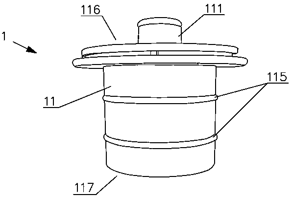
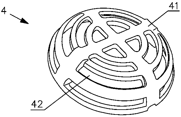
[0043] Such as Figure 9 As shown, the floor drain that is convenient for filtering hair includes a shell 2 made of metal material (stainless steel) and a seepage cover 3, and also includes a floor drain core 1 made of plastic material and a movable filter cover 4, and the movable filter cover 4 is located on the seepage cover 3 below. The housing 2 can be pre-installed on the ground. The housing 2 has a drainage channel d, and then the floor drain core 1 is inserted into the drainage channel d, and the movable filter cover 4 is placed, and the seepage cover 3 is finally covered. The function of the floor drain core 1 is to make the floor drain deodorize, prevent insects and filter hair; the function of the movable filter cover 4 is to filter the bulky impurities in the drainage; Impurities, protection movable filter cover 4 and floor drain core body 1. The casing 2 is provided with steps for the floor drain core 1 and the seepage cover 3 to be placed on.
[0044] Such as ...
Embodiment 2
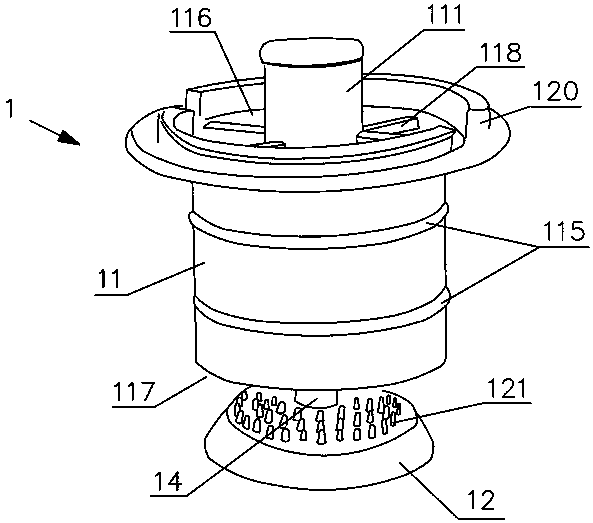
[0053] Such as Figure 5 The bottom support 12 in the shown embodiment 2, the difference between the embodiment 2 and the embodiment 1 is that the height of the hook teeth 121 arranged on the upper surface of the support body 122 (that is, the surface in the direction of the incoming liquid) changes, and the height of the hook teeth 121 The height gradually increases from the center of the bottom support 12 to the edge, Figure 5 The height (also can be understood as length) of the hook teeth 121 at c is greater than the height of the hook teeth 121 at b. In other technical solutions, the heights of two adjacent hook teeth 121 may also be the same in the above direction, but generally show a tendency to increase. This enhances hair filtering. Because the running water flows from above to the bottom bracket 12, and then flows to the periphery of the bottom bracket 12 under the blocking effect of the bottom bracket 12 and is discharged. The hair successfully intercepted by th...
Embodiment 3
[0055] Such as Image 6 Shown embodiment 3, embodiment 3 is similar to embodiment 1, and the difference with embodiment 1 is, on the support body 122 upper surface also is provided with dial 13, and the effect of dial 13 is to be able to quickly remove the hair when the subsequent sequence cleans up. The hair intercepted by the hook teeth 121 can be separated efficiently. The dial 13 is roughly disc-shaped, and its planar shape is as Figure 8 As shown, the center of the dial 13 is provided with a central hole 132 for the connecting rod 14 to pass through. The hair dial 13 is provided with a plurality of through holes 131. The distribution of the through holes 131 is consistent with the distribution of the hook teeth 121, and the hook teeth 121 can pass through. Through hole 131 . Such as Figure 7 As shown, the dial 13 can move along the hook teeth 121 . When the floor drain was working normally, the dial 13 was positioned at the root of the hook teeth 121, as Image 6 s...
PUM
 Abstract
Description
Claims
Application Information
 - R&D
- Intellectual Property
- Life Sciences
- Materials
- Tech Scout
- Unparalleled Data Quality
- Higher Quality Content
- 60% Fewer Hallucinations
Browse by: Latest US Patents, China's latest patents, Technical Efficacy Thesaurus, Application Domain, Technology Topic, Popular Technical Reports.
© 2025 PatSnap. All rights reserved.Legal|Privacy policy|Modern Slavery Act Transparency Statement|Sitemap|About US| Contact US: help@patsnap.com