Reinforcing structure between longitudinal and transverse walls of cold-formed thin-walled section steel house

A technology of cold-formed thin-walled steel and reinforced structures, which is applied in building construction and construction, and can solve problems such as structural collapse, failure of connections between walls and floors, failure of side and corner wall panels, etc., to achieve easy removal , enhance the anti-torsion ability of the side outside the plane, and improve the effect of anti-damage ability

Inactive Publication Date: 2018-11-06
SOUTHWEAT UNIV OF SCI & TECH
View PDF7 Cites 5 Cited by
  • Summary
  • Abstract
  • Description
  • Claims
  • Application Information

AI Technical Summary

Problems solved by technology

[0004] Chinese patent application No. 201611100380.1 discloses a cold-formed thin-walled steel beam-column structure system for multi-storey houses, including beams and wall frame columns that cooperate with each other. In this patent technology, H-shaped steel laminated welded composite reinforcement components and angle steel work together , can effectively improve the torsion resistance of the inner wall, but when the reinforcing component is applied to the wall, it can only improve the resistance of the wall at the connection between the floors
However, the low-cycle reciprocating loading test of the composite wall-composite floor slab connection shows that when the connection is loaded to the limit state of the bearing capacity, the self-tapping screws in the area between the wall and the floor slab will fail due to the reciprocating load, which will also cause edge failure. The failure of the wall panels at the top and corners will cause the failure of the connection between the wall and the floor, and induce the continuous collapse of the structure

Method used


Image

  • Reinforcing structure between longitudinal and transverse walls of cold-formed thin-walled section steel house
  • Reinforcing structure between longitudinal and transverse walls of cold-formed thin-walled section steel house
  • Reinforcing structure between longitudinal and transverse walls of cold-formed thin-walled section steel house

Examples


Embodiment Construction

[0041] The present invention will be described in detail below in conjunction with the accompanying drawings.

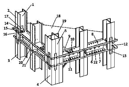
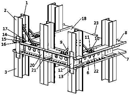
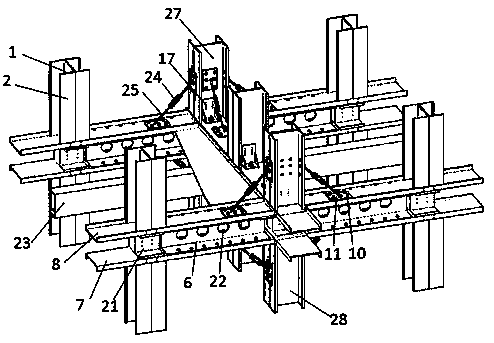
[0042] Such as figure 1 , figure 2 , image 3 , Figure 4 , Figure 5 and Figure 6 , a cold-formed thin-walled steel structure house wall strengthening method, characterized in that:

[0043] A reinforced structure between the vertical and horizontal walls of a cold-formed thin-walled steel house, including beams and wall frame columns that cooperate with each other:

[0044] The wall frame column includes the lower layer column and the upper layer column, which are composed of two C-shaped steel 2 that are back-to-back and fixed with self-tapping screws 13, and the corner wall wall frame columns are composed of four C-shaped steel 19 that are back-to-back and fixed with self-tapping screws 13 constitute;

[0045] The beams include a C-shaped steel floor beam 23, connecting the U-shaped steel top beam 7 of the lower building with the opening downwards of two...


PUM


Abstract

The invention discloses a reinforcing structure between longitudinal and transverse walls of a cold-formed thin-walled section steel house. The reinforcing structure comprises beams and wall frame columns, wherein the beams and the wall frame columns are mutually matched. The wall frame columns comprise lower-layer columns and upper-layer columns; the beams comprise floor beams (23), lower-layer house U-shaped beams (7) and upper-layer house U-shaped beams (8); the tops of the lower-layer columns are inlaid in openings of the U-shaped steel top beams (7) and fixed; the bottoms of the upper-layer columns are inlaid in openings of the U-shaped steel bottom beams (8) and fixed; the lower-layer columns and the upper-layer columns are connected through connecting pieces (12); anti-pulling pieces (17) are connected between the lower-layer columns and the U-shaped steel top beams (7), and anti-pulling pieces (17) are connected between the upper-layer columns and the U-shaped steel bottom beams (8); and H-shaped reinforcing components (6) between steel layers are connected between the U-shaped steel top beams (7) and the U-shaped steel bottom beams (8). The reinforcing structure is characterized in that oblique supporting pieces are connected between parts of the upper-layer columns and the U-shaped steel bottom beams (8) and/or oblique supporting pieces are connected between parts ofthe lower-layer columns and the U-shaped steel top beams (7).

Description

technical field [0001] The invention relates to an assembled cold-formed thin-walled steel building vertical and horizontal wall strengthening structure system, which is especially suitable for installation in low-rise and multi-layered assembled cold-formed thin-walled steel structure buildings, and belongs to the technical field of construction engineering. Background technique [0002] The load-bearing composite wall of cold-formed thin-walled steel houses is usually composed of cold-formed thin-walled steel wall frame columns, inner filling insulation cotton and outer covering gypsum board, etc., which is easy to realize resource recycling; wall panels have good thermal insulation performance , reduce energy consumption during use, and meet the national green environmental protection requirements; main components such as wall frame columns, floor beams, and wall panels are processed in the factory and then shipped to the site for assembly. The parts are light in weight, ...

Claims


Application Information

Patent Timeline
Patent Type & Authority Applications(China)
IPC IPC(8): E04B1/24E04B1/58
CPCE04B1/24E04B1/2403E04B2001/2418E04B2001/2448
Inventor 褚云朋姚勇陈晓强古松张兆强邓勇军杨东升
Owner SOUTHWEAT UNIV OF SCI & TECH
Why Eureka
Try Eureka