Slip form system for shaft concrete pouring and rock mass grouting

A concrete and sliding form technology, applied in shaft equipment, earthwork drilling, wellbore lining, etc., can solve the problems of short-range cross-interference and limited safety, and achieve the effect of platform safety, weight reduction, and avoidance of short-range cross-interference.

Pending Publication Date: 2018-11-06
SINOHYDRO BUREAU 7 CO LTD
View PDF4 Cites 5 Cited by
  • Summary
  • Abstract
  • Description
  • Claims
  • Application Information

AI Technical Summary

Problems solved by technology

Since the hoop reinforcement can only be installed below the column head (F-type climbing pole), the installation of the hoop reinforcement is affected by the sliding speed of the concrete. Conversely, the sliding speed of the concrete is also restricted by the installation speed of the hoop reinforcement, resulting in concrete construction. The short-distance cross-interference with the installation and construction of steel bars needs to be further solved to increase the speed; at the same time, because the climbing rod rises synchronously with the concrete and is buried in the concrete, the sliding form body only has the function of one-time use, resulting in the later rock wall solidification. Knot grouting is often constructed in hanging baskets, hanging baskets or other forms, which are limited in safety and progress. Therefore, the construction process needs to be further optimized

Method used


Image

  • Slip form system for shaft concrete pouring and rock mass grouting
  • Slip form system for shaft concrete pouring and rock mass grouting
  • Slip form system for shaft concrete pouring and rock mass grouting

Examples


Embodiment Construction

[0031] The present invention is further described below in conjunction with specific embodiment, and specific embodiment is the further description of the principle of the present invention, does not limit the present invention in any way, and the identical or similar technology of the present invention all does not exceed the scope of protection of the present invention.

[0032] In conjunction with the accompanying drawings.

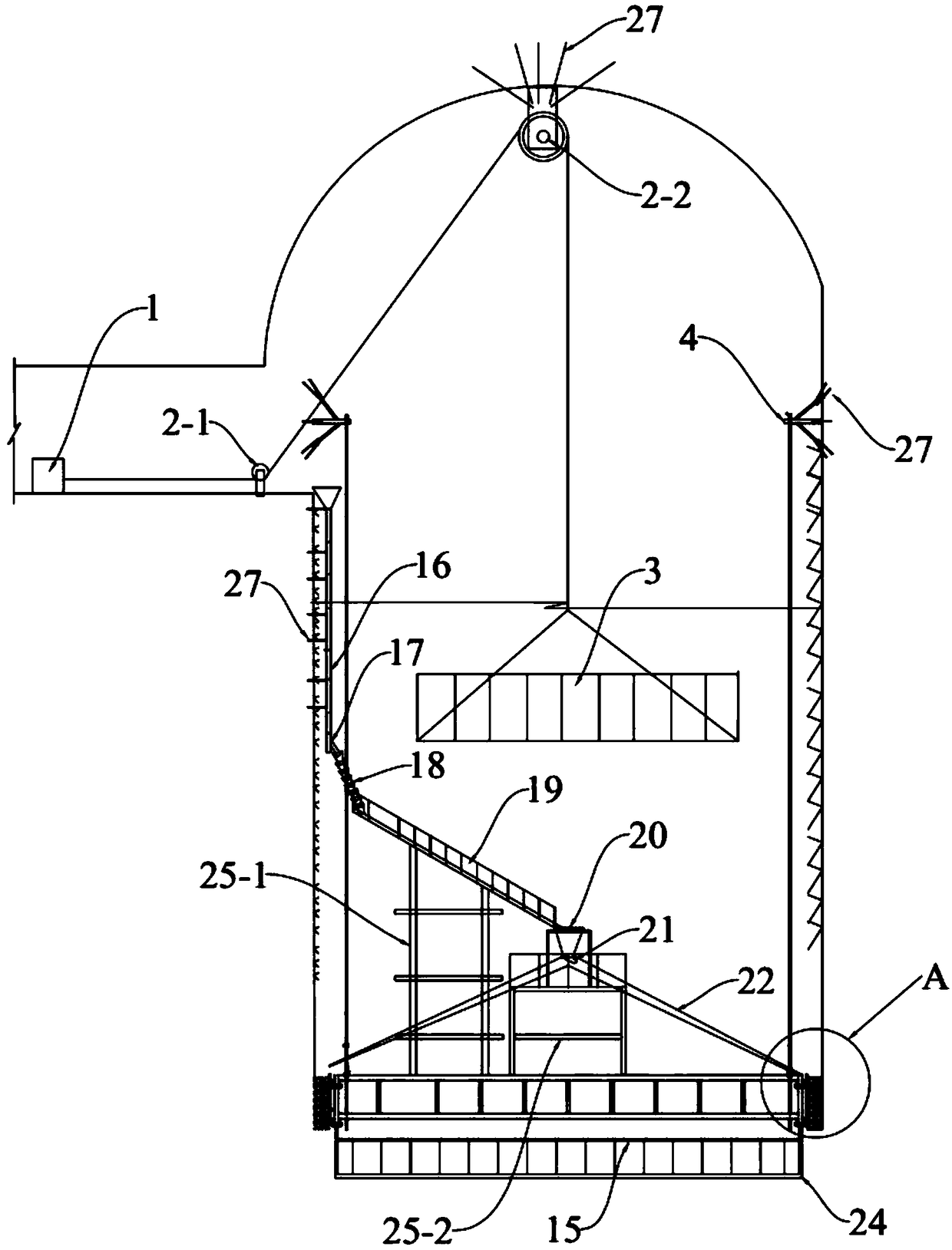
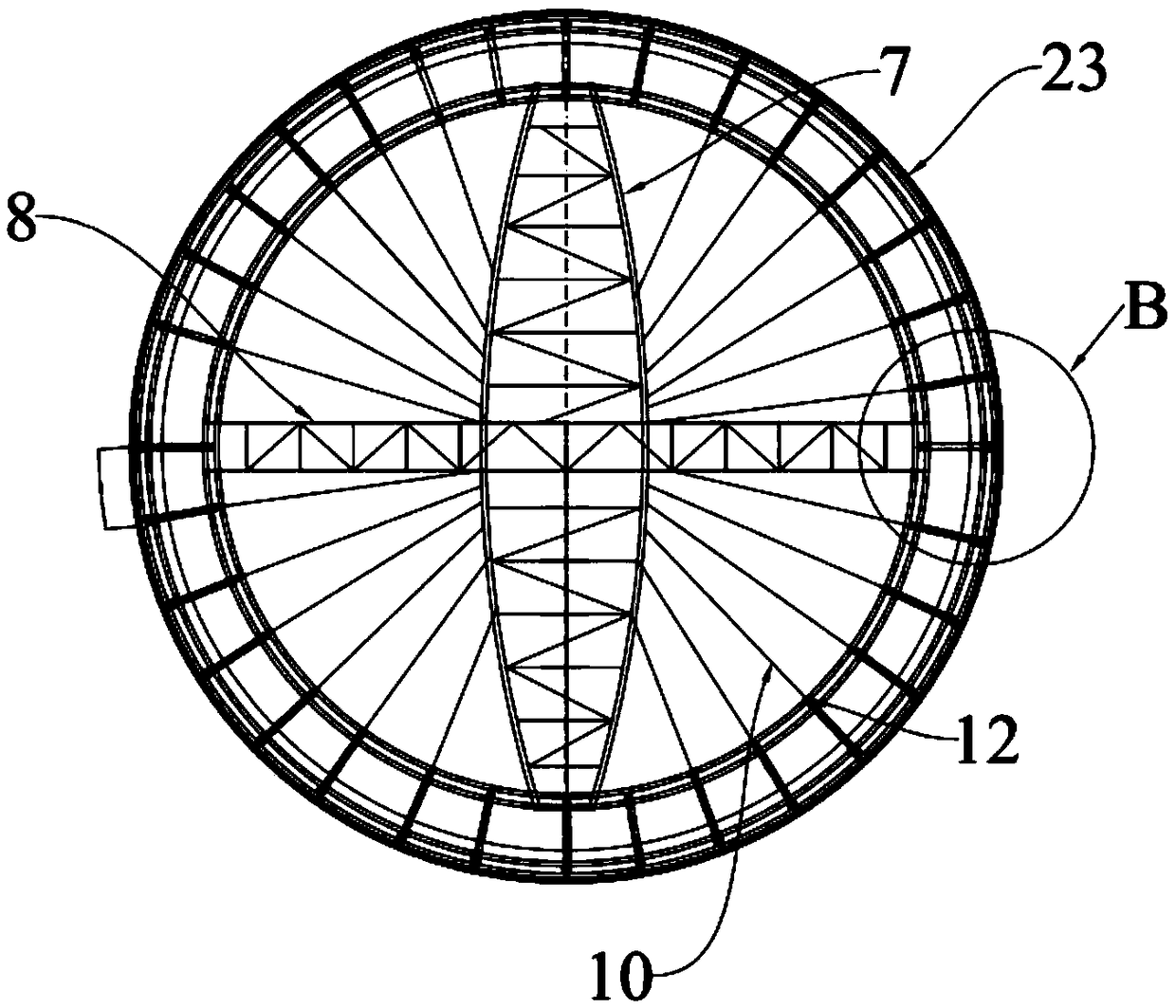
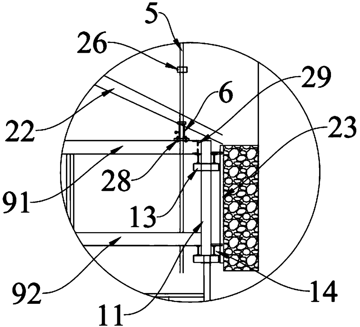
[0033] Slipform system for shaft concrete pouring and rock mass grouting, including pouring grout delivery system, formwork system composition and formwork moving system; pouring grout delivery system is used for delivery of shaft concrete or rock mass grouting material, formwork system is used for shaft Concrete pouring or rock mass grouting formwork lining and its support, the formwork moving system is used to drive the formwork movement in the shaft concrete pouring or grouting process.

[0034] The formwork system of the present invention is compos...


PUM


Abstract

The invention discloses a slip form system for shaft concrete pouring and rock mass grouting. The slip form system comprises a pouring grouting conveying system, a formwork system and a formwork moving system. The slip form system adopts externally-climbing hydraulic slip forms to solve the problem that the speed of construction is affected by the close-distance cross interference between the steel bar installation and the concrete construction in conventional shaft concrete slip form construction. Steel bars of the slip form system can be installed in advance of the working face of concrete construction more than 6.0 m to avoid the close-distance cross interference between concrete and steel bar construction, so that the slipping rising speed is high. The slip form system adopts climbingrod external suspension, form bodies can be lowered and used repeatedly after slipping rising, recycling is achieved, so that the using number of climbing rods can be saved, a basket does not need tobe manufactured and installed during application, the slip form system is composed of synchronously-driven balanced moving formwork systems of hydraulic jacks, and dismountable limiters located on thesame horizontal plane are arranged on the climbing rods to ensure the balanced, stable and safe movement of formworks and control the formworks more accurately.

Description

technical field [0001] The invention relates to the technical field of concrete and grouting construction, in particular to a slip form structure system for vertical shaft concrete pouring and rock mass grouting. Background technique [0002] At present, the construction of tall and large shaft concrete and grouting usually starts with shaft concrete slipform. And when carrying out slipform construction to shaft concrete, be to bury climbing rod first in concrete, then hydraulic jack is sleeved on the climbing rod, then hydraulic jack is connected with formwork and supporting platform as a whole. When sliding up, the hydraulic jack is pressurized and shrinks up, and the hydraulic jack keeps a certain distance from the concrete surface to meet the needs of the installation of the circumferential reinforcement. Since the hoop reinforcement can only be installed below the column head (F-type climbing pole), the installation of the hoop reinforcement is affected by the sliding ...

Claims


Application Information

Patent Timeline
IPC IPC(8): E21D5/11E21D5/12
CPCE21D5/11E21D5/12
Inventor 王强罗宁彭世成王焕强李霞李勇董树荣王再强
Owner SINOHYDRO BUREAU 7 CO LTD
Why Eureka
Try Eureka