
Whole-process automatic tracking dust-removal system for smelting furnace and realization method thereof

A fully automatic, dust removal system technology, applied in furnaces, furnace components, waste heat treatment, etc., can solve problems such as poor dust collection effect, hindering the normal operation of smelting furnaces, and being easily damaged by high temperature

Inactive Publication Date: 2018-11-06
昌邑恒昌新材料科技有限公司
View PDF5 Cites 0 Cited by
  • Summary
  • Abstract
  • Description
  • Claims
  • Application Information

AI Technical Summary

Problems solved by technology

Even if it is installed, because the height and position of the smelting furnace change during the working process, the height of the vacuum hood is too close to the furnace mouth, and the dust collection effect is good, but it is easy to be damaged by high temperature and hinders the normal operation of the smelting furnace. work; too high and the vacuum effect is not good; basically nothing
[0006] This does not comply with the "Environmental Protection Law", especially if the dust content is not greater than 15mg / m 3 standard

Method used


Image

  • Whole-process automatic tracking dust-removal system for smelting furnace and realization method thereof
  • Whole-process automatic tracking dust-removal system for smelting furnace and realization method thereof
  • Whole-process automatic tracking dust-removal system for smelting furnace and realization method thereof

Examples


Embodiment 1

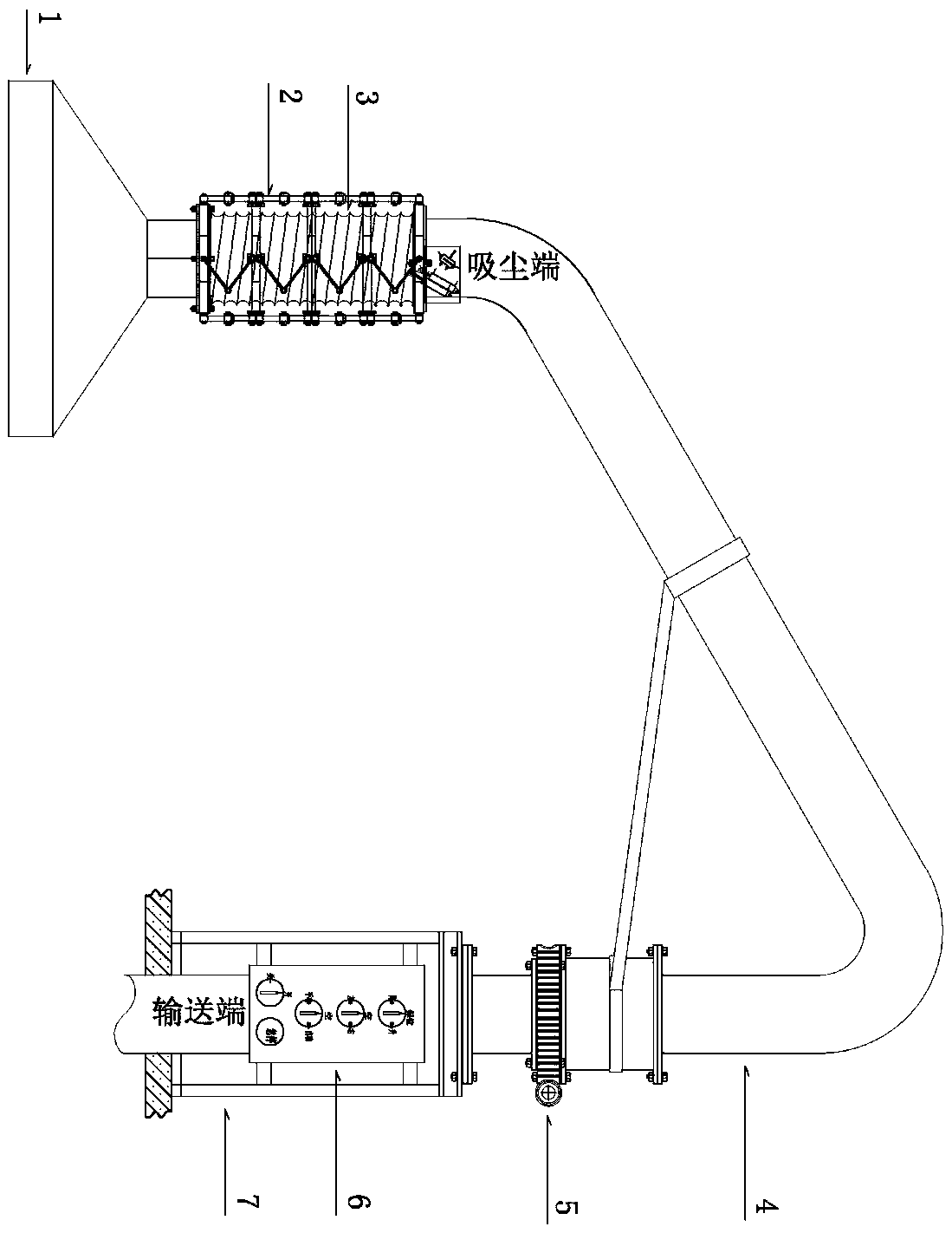
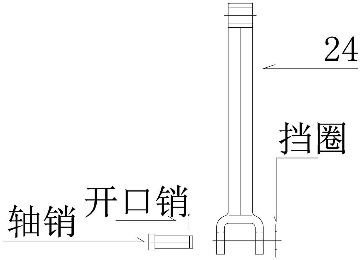
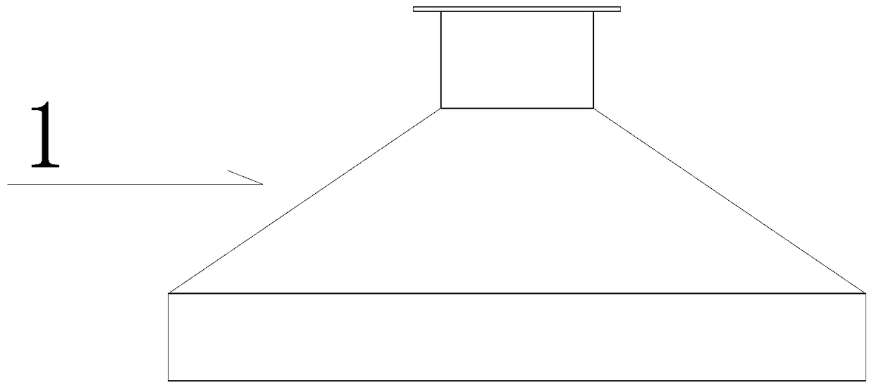
[0096] Example 1, such as Figure 1 to Figure 34 As shown, a whole-process automatic tracking dust removal system for a smelting furnace includes a cage type telescopic frame group 2, a dust collection cover 1, a high temperature resistant telescopic pipe 3, a dust suction pipe 4, a slewing bearing 5, an operation panel 6 and a fixed frame 7, and is resistant to The high temperature telescopic tube 3 is connected to the suction end of the dust collection cover 1 and the dust collection pipe 4, the high temperature resistant telescopic tube 3 is inserted into the cavity of the cage type telescopic frame group 2, the dust collection cover 1 is connected to the cage type telescopic frame group 2, The delivery end of the dust suction pipe 4 is connected with the slewing bearing 5 .

[0097] The cage telescopic frame group 2 includes double-acting cylinder group 23, 26# swing rod group 26, 27# swing rod group 27, 21# cage frame 21, 28# cage frame 28, 29# cage frame 29, 24# swing r...


PUM


Abstract

The invention discloses a whole-process automatic tracking dust-removal system for a smelting furnace and a realization method thereof. The whole-process automatic tracking dust-removal system comprises a cage-type telescopic frame set, a dust suction hood, a high-temperature-resisting telescopic pipe, a dust suction pipeline and a rotary support; the high-temperature-resisting telescopic pipe isconnected with the dust suction ends of the dust suction hood and the dust suction pipeline; and the high-temperature-resisting telescopic pipe is sleeved with a cavity of the cage-type telescopic frame set, the dust suction hood is connected with the cage-type telescopic frame set, and the conveying end of the dust suction pipeline is connected with the rotary support. The whole-process automatictracking dust-removal system has the following advantages that a whole-process automatic tracking function is achieved, the optimal dust removal effect is ensured, labor is saved, the misoperation phenomenon is avoided, an oil cylinder is replaced with an air cylinder, thus flammability of oil is avoided, the whole-process automatic tracking dust-removal system can work under the flammable environment, the cost of multiple cylinders is saved, and the double-acting air cylinder has power in extending and retracting, lifting movement of the suspended load and objects loaded on an inner cavity of a cage-type frame are achieved, the reasonable distance can be kept between the dust suction hood and a furnace cover through the telescopic function, and the optimal dust removal effect is achieved.

Description

technical field [0001] The invention relates to a dust removal system, in particular to a whole-process automatic tracking dust removal system for a smelting furnace. Background technique [0002] Foundry industry and amorphous alloy industry use electric furnace to smelt molten steel. Electric furnace smelting (hereinafter referred to as smelting furnace) will produce smoke and dust pollution during the working process. Some smelting furnaces have a dust suction system on the furnace cover, and some smelting furnaces have There is no vacuum system. [0003] For smelting furnaces with a dust suction system on the furnace cover, during the smelting process, feeding process, temperature measurement process, and pouring of molten steel, there will be smoke and dust that is not sucked away, but will be emitted into the surrounding environment. [0004] In the smelting furnace without dust suction system on the furnace cover, the smoke and dust in the whole process will be distr...

Claims


Application Information

Patent Timeline
IPC IPC(8): F27D17/00
CPCF27D17/001
Inventor 滕麟群朱建华
Owner 昌邑恒昌新材料科技有限公司
Learn More