Optical displacement sensor device and measuring scale with same

A technology of displacement sensor and sensor, which is applied in the field of measurement, can solve problems such as the inability to use transparent solutions for accurate measurement, and achieve the effect of meeting high-precision requirements

Pending Publication Date: 2018-11-06
宿迁天海数字测控技术有限公司 +1
View PDF5 Cites 2 Cited by
  • Summary
  • Abstract
  • Description
  • Claims
  • Application Information

AI Technical Summary

Problems solved by technology

[0003] In order to solve the problem that it cannot be used in transparent solution for accurate measurement, the present invention provides an academic displacement sensor device and a measuring ruler using the above sensor device, which can be used for measurement in transparent solution and meet the high precision requirements

Method used


Image

  • Optical displacement sensor device and measuring scale with same
  • Optical displacement sensor device and measuring scale with same
  • Optical displacement sensor device and measuring scale with same

Examples


Embodiment 1

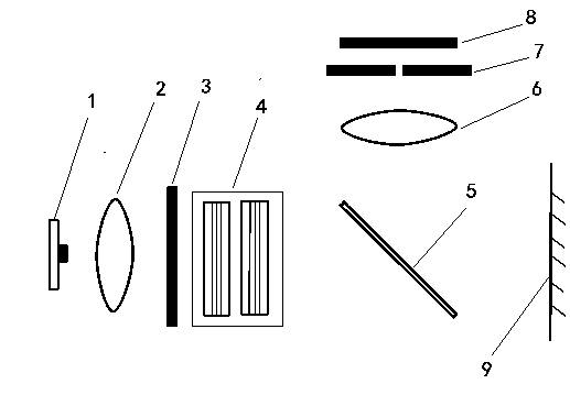
[0022] Embodiment one: see figure 1 As shown, a measuring ruler using the above-mentioned optical displacement sensor device includes a fixed ruler and a moving ruler, and the moving ruler includes a light source part, a half mirror 5, and an imaging part arranged in a sealed cover, and the imaging part includes sequentially Arranged imaging lens 6, diaphragm 7 and CCD sensor 8, the moving ruler is arranged above the fixed ruler 9, and the ruler surface of the fixed ruler 9 is provided with measurement marks, and the light source part includes a monochromatic light source 1 arranged in sequence, a uniformly collimated Lens 2, shading plate 3 and light-condensing collimating lens 4, the light that monochromatic light source 1 sends and passes through semi-reflective half lens 5 is perpendicular to the ruler face of fixed ruler 9, and uniform collimating lens 2 is used for sending out monochromatic light source The light becomes parallel light, and the semi-reflective half lens ...

Embodiment 2

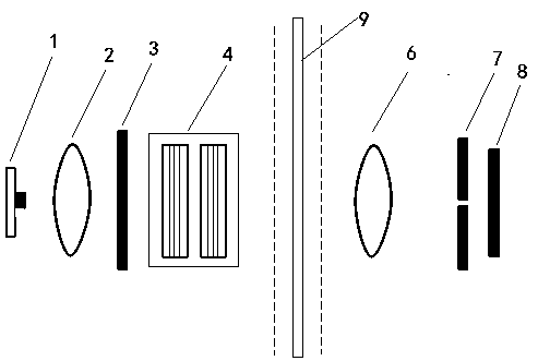
[0024] Embodiment 2: a measuring ruler using the above-mentioned optical displacement sensor device, which includes a fixed ruler 9 and a moving ruler. The movable ruler includes a light source part arranged on one side of the fixed ruler and an imaging part arranged on the other side of the fixed ruler. The ruler body is a transparent structure and measuring marks are arranged on the ruler surface. The light emitted by the monochromatic light source 2 and passed through the collimating lens is perpendicular to the ruler surface of the fixed ruler 9. The rest of the settings are the same as in the first embodiment. A row of sheet metal is plated on the scale face of the fixed length 9.

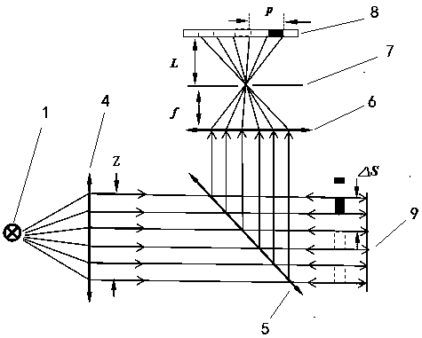
[0025] its optical path see Figure 4 As shown, similarly, when the moving distance of the moving ruler relative to the fixed ruler is △S, its imaging has moved a displacement p on the CCD sensor, and the moving distance of the moving ruler relative to the fixed ruler can be obtained by proces...


PUM


Abstract

The invention relates to an optical displacement sensor device and a measuring scale with the same, and belongs to the technical field of measurement. The optical displacement sensor device can be used to measure a transparent solution and satisfy the requirement of high precision. The optical displacement sensor device comprises a light source part and an imaging part, the light source part comprises a monochromatic light source and a collimating lens, the collimating lens changes light emitted by the monochromatic light source into parallel light, the imaging part comprises an imaging lens,a diaphragm and a CCD sensor arranged sequentially, the CCD sensor converts a received optical signal into an electric signal for displacement measurement, and a sealed cover is arranged outside the light source part and the imaging part. The measuring scale with the optical displacement sensor device comprises a static ruler and a moving ruler, the moving ruler comprises the light source part arranged at one side of the static ruler and the imaging part arranged in the other side of the static ruler, or the light source part, a semi-reflective semi-transparent mirror and the imaging part arranged in the sealed cover, and the moving ruler is arranged over the static ruler.

Description

technical field [0001] The invention relates to the field of measurement technology, and can be used for precise displacement measurement on a small scale, in particular to an optical displacement sensor device and a measuring ruler using the sensor device. Background technique [0002] At present, there are many types of digital display vernier calipers on the market. The main sensors used are: capacity displacement sensor, magnetic displacement sensor, eddy current displacement sensor, magnetoresistive displacement sensor, etc. The above-mentioned sensors have relatively low requirements for use. For example, magnetic displacement sensors can be used in different liquid media, because most of the media have similar magnetic permeability. Compared with the above-mentioned sensors, optical displacement sensors are generally used in occasions with higher precision, but for The environmental requirements are also relatively harsh. Due to the refraction phenomenon in the optica...

Claims


Application Information

Patent Timeline
Patent Type & Authority Applications(China)
IPC IPC(8): G01B11/02
CPCG01B11/02
Inventor 阙婷婷
Owner 宿迁天海数字测控技术有限公司
Why Eureka
Try Eureka