Method for non-contact measurement of displacement of tamping apparatus of railway track lifting and lining tamping wagon

A non-contact, measuring device technology, applied in the direction of measuring devices, optical devices, instruments, etc., can solve problems such as failure, complex mechanical structure, loose mechanical parts of sensors, etc., and achieve the effect of saving measurement cost and prolonging service life

Inactive Publication Date: 2018-11-06
长沙瀚鹏电子技术有限公司
View PDF0 Cites 2 Cited by
  • Summary
  • Abstract
  • Description
  • Claims
  • Application Information

AI Technical Summary

Problems solved by technology

[0004] The purpose of the present invention is to provide a non-contact method for measuring the displacement of the tamping device of the railway tamping vehicle, so as to solve the complex and precise internal mechanical structure of the existing sensor proposed in the background technology, and the tamping vehicle operation When the car body vibrates violently, it is easy to cause the internal mechanical parts of the sensor to loosen, resulting in a decrease in the measurement accuracy of the sensor or even a complete failure. In addition, when the tamping vehicle is in operation, the tamping device must perform about 1300 reciprocating movements per hour, and the number of times the coil spring expands and contracts is limited, so the working life of this sensor is relatively short, and it needs to be replaced frequently

Method used


Image

  • Method for non-contact measurement of displacement of tamping apparatus of railway track lifting and lining tamping wagon
  • Method for non-contact measurement of displacement of tamping apparatus of railway track lifting and lining tamping wagon
  • Method for non-contact measurement of displacement of tamping apparatus of railway track lifting and lining tamping wagon

Examples


Embodiment Construction

[0026] The technical solutions in the embodiments of the present invention will be clearly and completely described below in conjunction with the accompanying drawings in the embodiments of the present invention. Obviously, the described embodiments are only a part of the embodiments of the present invention, rather than all the embodiments. Based on the embodiments of the present invention, all other embodiments obtained by those of ordinary skill in the art without creative work shall fall within the protection scope of the present invention.

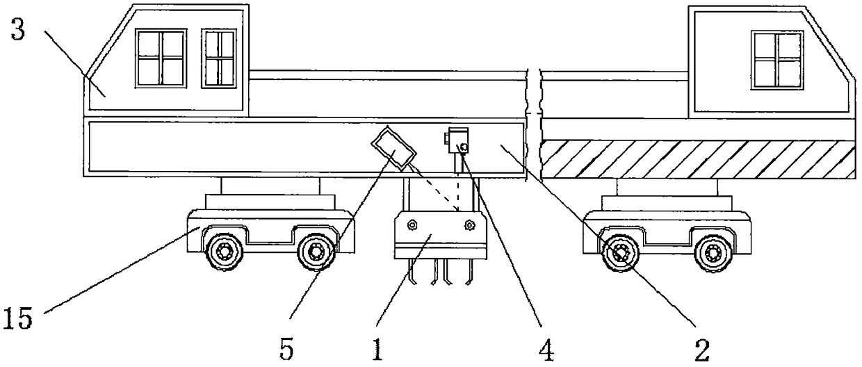
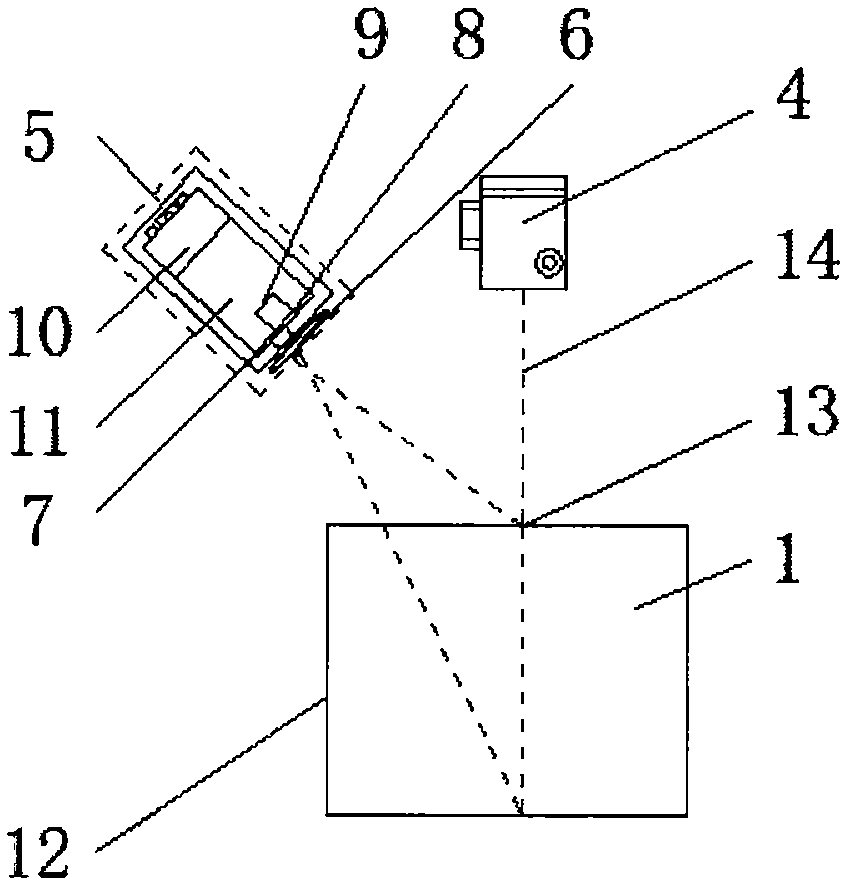
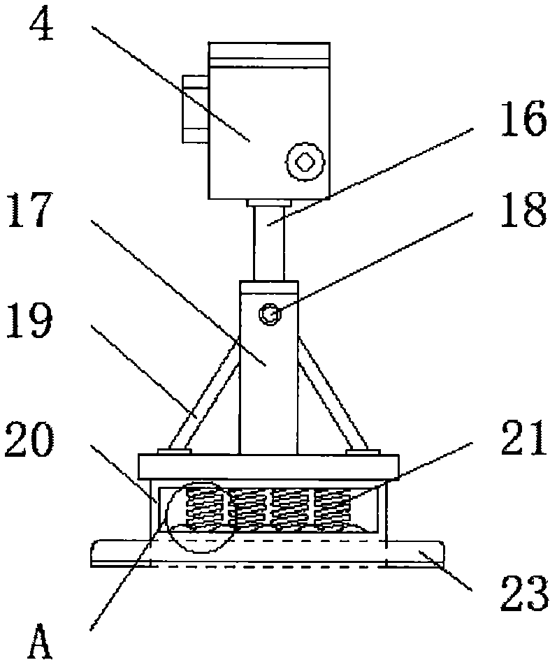
[0027] See Figure 1-5 , The present invention provides a technical solution: a non-contact method for measuring the displacement of a tamping device of a tamping car on a railway pull-out track, comprising a tamping device 1, a tamping car beam 2, a tamping car 3, and a laser transmitter 4 , CCD measuring device 5, optical lens 6, CCD sensor 7, image 8, displacement 9, signal output interface 10, algorithm module 11, actual displacement...


PUM


Abstract

The invention relates to a method for non-contact measurement of the displacement of a tamping apparatus of a railway track lifting and lining tamping wagon. According to the method, the tamping apparatus, a CCD sensor and a signal output interface are included, the upper end of the tamping apparatus is provided with a tamping wagon crossbeam, the tamping wagon is fixed at the external part of thetamping wagon crossbeam, the upper end of the tamping wagon crossbeam is provided with a laser emitter and a CCD measuring apparatus, the internal part of the CCD measuring apparatus is provided withan optical lens, the CCD sensor is arranged above the optical lens, and the upper end of the CCD sensor displays an image. According to the method for non-contact measurement of the displacement of the tamping apparatus of the railway track lifting and lining tamping wagon, the image corresponds to the position of the tamping apparatus in the CCD sensor, laser spots can be reflected to the optical lens of the CCD measuring apparatus through the surface of the tamping apparatus and imaged on the CCD sensor, the laser spots are emitted to the CCD sensor through the optical lens of the CCD measuring apparatus to generate the image, and vertical displacement of the tamping apparatus relative to the tamping wagon crossbeam is accurately calculated through a relation between the displacement amount and the practical displacement.

Description

Technical field [0001] The invention relates to the technical field of tamping vehicles, in particular to a non-contact method for measuring the displacement of a tamping device of a tamping vehicle for a railway pick-up track. Background technique [0002] The tamping car is a type of large-scale road maintenance machinery (large machine for short), which is suitable for the construction of new lines of railway lines, the large and medium repair and screening operations of existing lines, and the maintenance operations of operating lines. It reciprocates up and down in the vertical direction. In order to ensure the quality of work, the rising and falling positions and positions of the tamping device need to be accurately controlled. For this reason, it is necessary to accurately measure the displacement of the tamping device in real time. The current methods for measuring this displacement are all contact The method is to install a sensor composed of a potentiometer, gear transm...

Claims


Application Information

Patent Timeline
IPC IPC(8): G01B11/02
CPCG01B11/02
Inventor 马世宏
Owner 长沙瀚鹏电子技术有限公司
Why Eureka
Try Eureka