
Welding quality detection device and detection method thereof

A detection device and welding quality technology, applied in the field of circuit board processing, can solve problems such as misjudgment, affecting the accuracy of judging structure, and density

Active Publication Date: 2018-11-06
GUANGZHOU FASTPRINT CIRCUIT TECH +2
View PDF43 Cites 4 Cited by
  • Summary
  • Abstract
  • Description
  • Claims
  • Application Information

AI Technical Summary

Problems solved by technology

[0003] At present, the detection process of connector welding quality is inefficient, and it is usually carried out by visual inspection, that is, the staff checks with the naked eye whether the connector welding meets the established requirements
The visual detection method is not only inefficient, but also the quality of detection is unstable. The unfavorable factors of using naked eye detection include:
[0004] 1. When the staff looks at the same item for a long time, it is easy to misread or miss the situation, and the good ones are bad, and the bad ones are good, leading to misjudgment;
[0005] 2. Visual inspection mainly depends on the subjective judgment of the staff, which affects the accuracy of the judgment structure, and cannot achieve the effect of unifying the testing standards of machine testing and more accurate testing results;
[0006] 3. The working status and personal emotions of the staff may affect the efficiency and quality of testing;
[0007] 4. The welding feet of the connector are not only small but also dense, and excessive use of eyes for a long time is not good for the physical and mental health of employees

Method used


Image

  • Welding quality detection device and detection method thereof
  • Welding quality detection device and detection method thereof
  • Welding quality detection device and detection method thereof

Examples


Embodiment Construction

[0035] Embodiments of the present invention are described in detail below in conjunction with accompanying drawings:

[0036] It should be noted that when an element is “fixed” to another element, it may be directly on the other element or there may be an intervening element. When an element is referred to as being "connected to" another element, it can be directly connected to the other element or intervening elements may also be present. In contrast, when an element is referred to as being "directly on" another element, there are no intervening elements present. The terms "vertical," "horizontal," "left," "right," and similar expressions are used herein for purposes of illustration only and are not intended to represent the only embodiments.

[0037] Unless otherwise defined, all technical and scientific terms used herein have the same meaning as commonly understood by one of ordinary skill in the technical field of the invention. The terminology used herein in the descrip...


PUM


Abstract

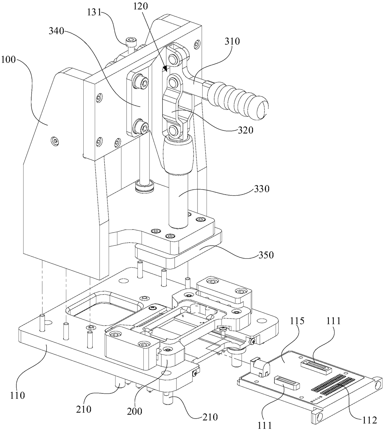
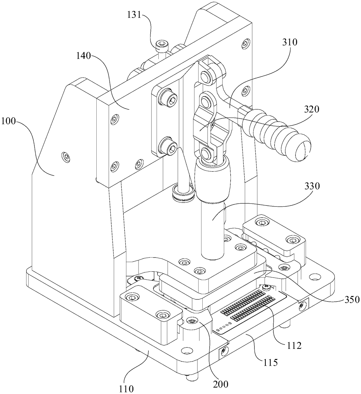
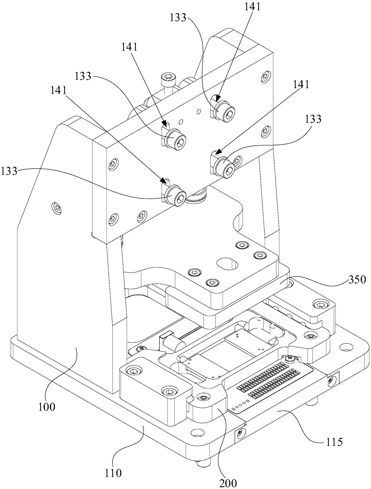
The invention relates to a welding quality detection device and a detection method thereof. The welding quality detection device comprises a mounting rack, a loading piece and a driving mechanism, wherein the mounting rack is provided with a detection platform; the detection platform is provided with a detection plug; the detection plug is provided with a detection slot; the groove of the detection slot is internally provided with an inserting part and a testing probe. The detection method comprises the following steps: firstly moving the loading piece to a first preset position by the drivingmechanism so that the welding part of a product to be detected is matched with the inserting part, and then moving the loading piece to a second preset position by the driving mechanism so that the welding part of the product to be detected is matched with the testing probe so as to test whether welding is qualified. Due to the fact that the welding part is firstly matched with the inserting part, if the problem such as welding instability exists in the welding part, frictional force generated in the inserting process can enable an instable part to fall off, and the welding part cannot be passed when the welding part is matched with the testing probe for testing in later period, so that the testing result whether the welding part is qualified is obtained. Artificial viewing of naked eyesis not needed by using the mechanism, so that the welding detection efficiency is improved, and the production cost is also reduced.

Description

technical field [0001] The invention relates to the technical field of circuit board processing, in particular to a welding quality detection device and a detection method thereof. Background technique [0002] Connectors, also known as connectors, plugs or sockets, usually refer to electrical connectors, which are used to connect two active devices to transmit current or signals. The production of connectors includes a welding process, and the connectors welded to the circuit board need to test whether the welding effect and welding stability are up to standard. [0003] At present, the detection process of connector welding quality is inefficient, and it is usually carried out by visual inspection, that is, the staff checks with the naked eye whether the connector welding meets the established requirements. The visual detection method is not only inefficient, but also the quality of detection is unstable. The unfavorable factors of using naked eye detection include: [0...

Claims


Application Information

Patent Timeline
Patent Type & Authority Applications(China)
IPC IPC(8): G01N27/00G01R31/01
CPCG01N27/00G01R31/01
Inventor 欧云松吴林汉雷勇锋
Owner GUANGZHOU FASTPRINT CIRCUIT TECH
Learn More