Test system for simulating degradation law of dynamic soil arching effects

A test system and soil arching effect technology, applied in the field of railway engineering, can solve the problems of instability, affecting the load sharing between piles and soil in the subgrade, and inability to judge the flow trend of soil particles, so as to improve the test accuracy, ensure safety, maintain The effect of convenience

Inactive Publication Date: 2018-11-06
TONGJI UNIV
View PDF14 Cites 9 Cited by
  • Summary
  • Abstract
  • Description
  • Claims
  • Application Information

AI Technical Summary

Problems solved by technology

However, as the dynamic load continues to act, the soil arching effect may change, it may be stable, or it may be unstable, and the state of instability may be instantaneous or a gradual process
These different changes will further affect the load sharing between piles and soil in the subgrade, and affect the service performance of the subgrade
[0004] The research on the soil arch effect under dynamic load is still in its infancy. Most scholars only studied the distribution and change law of the soil arch effect stress field under dynamic load, but did not give more information on the displacement field. Conclusion, especially the quantitative analysis method of geotechnical effect under long-term dynamic load, so it is urgent to explore the law and correlation of stress field and displacement field when soil arch effect changes under dynamic load
In addition, in the experiment of the dynamic soil arching effect, the previous observations on the displacement field of the soil arching effect were mainly based on laying colored sand to take photos and importing them into CAD for analysis, but the flow trend of soil particles could not be judged, so It is difficult to reveal the development and change law of the displacement field

Method used


Image

  • Test system for simulating degradation law of dynamic soil arching effects
  • Test system for simulating degradation law of dynamic soil arching effects
  • Test system for simulating degradation law of dynamic soil arching effects

Examples


Embodiment

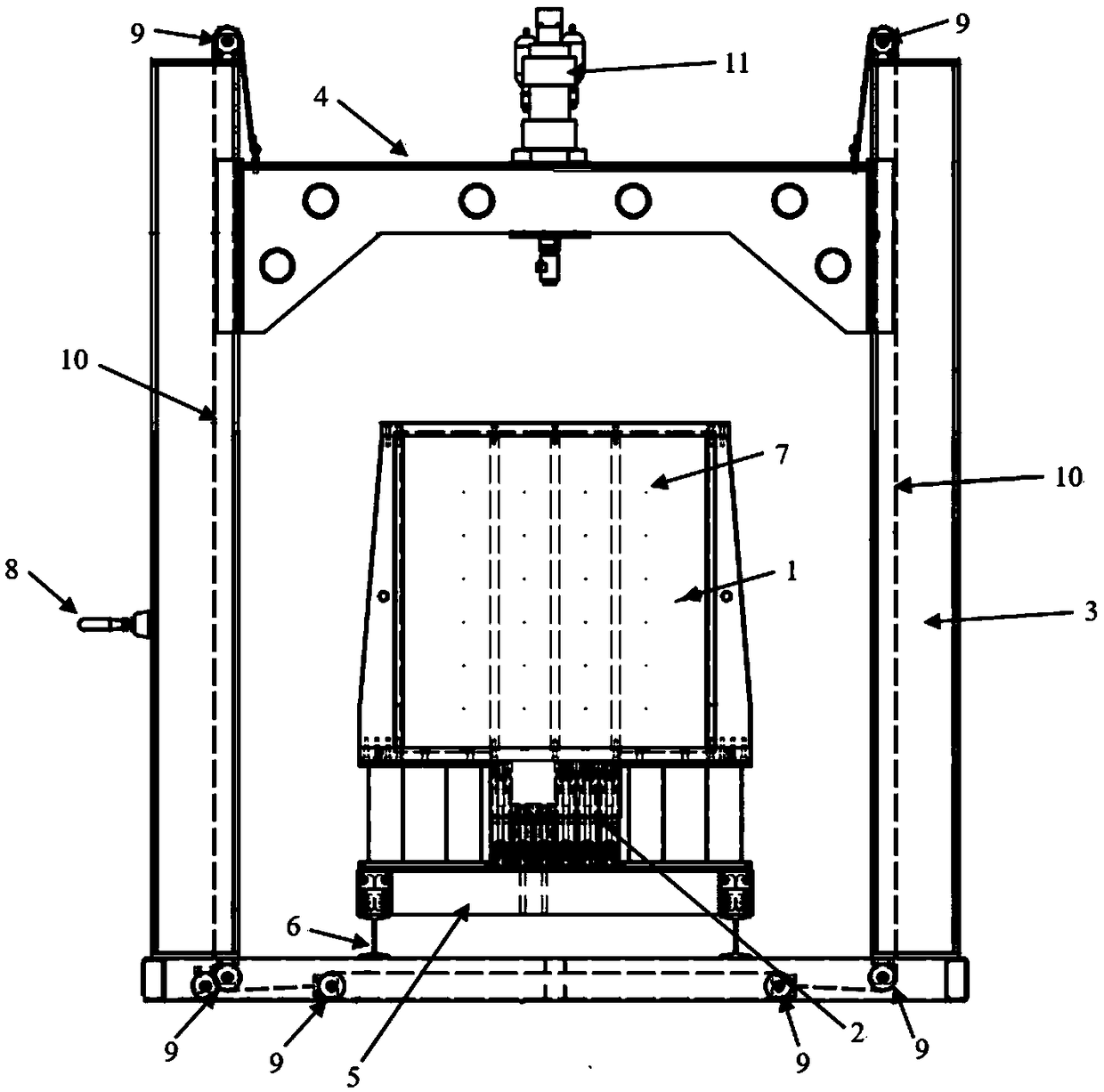
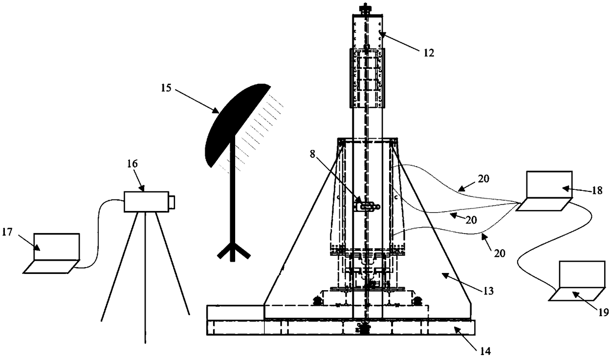
[0027] A test system for simulating the degradation law of dynamic soil arching effect, the structure is as follows figure 1 As shown, it is mainly composed of loading equipment, observation equipment, testing equipment and adjustment equipment. The equipment simulates servo actuators with different frequencies and load amplitudes, the observation equipment is a PIV digital image processing system for observing the cross-sectional displacement field and the flow trend of soil particles, and the testing equipment is a film single-point stress sensor arranged in the soil arch effect area.

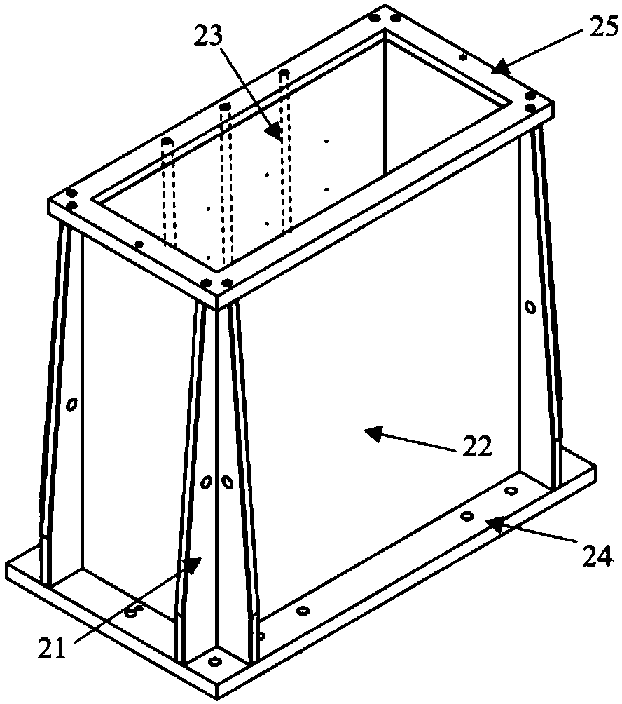
[0028] Specifically, the adjustment equipment is composed of a model box 1, a movable door adjustment device 2, a test bench and a reaction frame. The structure of the model box 1 is as follows: image 3 As shown, the 20mm thick plexiglass plate 22 is used as the material of the model box. On the one hand, because the transparent plexiglass plate has good perspective, on the other hand, becau...


PUM

PropertyMeasurementUnit
thicknessaaaaaaaaaa
diameteraaaaaaaaaa

Abstract

The invention relates to a test system for simulating a degradation law of dynamic soil arching effects, the test system is composed of a loading device, an observation device, a testing device and anadjusting device. The loading device controls load loading on the adjusting device, and the observation device is arranged on one side of the adjusting device. The testing device is used for testing.Compared with the prior art, the test system can improve the testing of the dynamic soil arching effects, realize the simultaneous observation of different degrees of soil arching effects, stress fields and displacement fields, and realize the change of different levels of factors. The test system can improve the test accuracy and maintain the convenience of operation.

Description

technical field [0001] The invention belongs to the field of railway engineering, and in particular relates to a device which can be used to simulate the change law of soil arch effect stress field and displacement field when a dodge door generates downward displacement under the action of dynamic load. Background technique [0002] When studying engineering problems, the real site is often simulated by means of experiments, so as to obtain certain laws and help to explore the mechanism of the phenomenon. Compared with field test or full-scale test, model test can reduce the test scale, so as to realize the simulation under different working conditions, and has the characteristics of small scale, short cycle and low cost. Therefore, in order to achieve the test purpose, it is necessary to design different test equipment. When designing test equipment, in addition to realizing the various conditions and purposes of the test, it should also take into account the convenience, ...

Claims


Application Information

Patent Timeline
Patent Type & Authority Applications(China)
IPC IPC(8): G01N33/24
CPCG01N33/24
Inventor 宫全美程茜毕宗琦
Owner TONGJI UNIV
Why Eureka
Try Eureka