Communication engineering optical fiber switching box

A communication engineering and switch box technology, applied in the field of switch boxes, can solve problems such as poor cooling effect of cooling holes, entry into the inside of the switch box, damage to internal equipment, etc., to improve ventilation and heat dissipation effects, facilitate stable work, and increase service life Effect

Active Publication Date: 2018-11-06
马鞍山方融信息科技有限公司
View PDF13 Cites 1 Cited by
  • Summary
  • Abstract
  • Description
  • Claims
  • Application Information

AI Technical Summary

Problems solved by technology

[0002] With the prosperity of the society and the rapid development of the network, network equipment has become an indispensable equipment in people's life. It is loved by people for its advantages of fast data transmission. The optical fiber switch box is the infrastructure of the network. A stable and fast network needs to rely on the optical fiber switch box. Many of the existing fiber optic cable switch boxes are installed outdoors, and there are many cooling holes on the fiber optic cable switch box to facilitate the cooling of the equipment running inside the switch box. However, the heat dissipation effect of the heat dissipation holes is not good, and the external dust and rainwater are easy to enter the inside of the exchange box through the heat dissipation holes, thereby causing damage to the internal equipment and making it inconvenient to use

Method used


Image

  • Communication engineering optical fiber switching box
  • Communication engineering optical fiber switching box
  • Communication engineering optical fiber switching box

Examples


Embodiment Construction

[0022] The following will clearly and completely describe the technical solutions in the embodiments of the present invention with reference to the accompanying drawings in the embodiments of the present invention. Obviously, the described embodiments are only some, not all, embodiments of the present invention. Based on the embodiments of the present invention, all other embodiments obtained by persons of ordinary skill in the art without making creative efforts belong to the protection scope of the present invention.

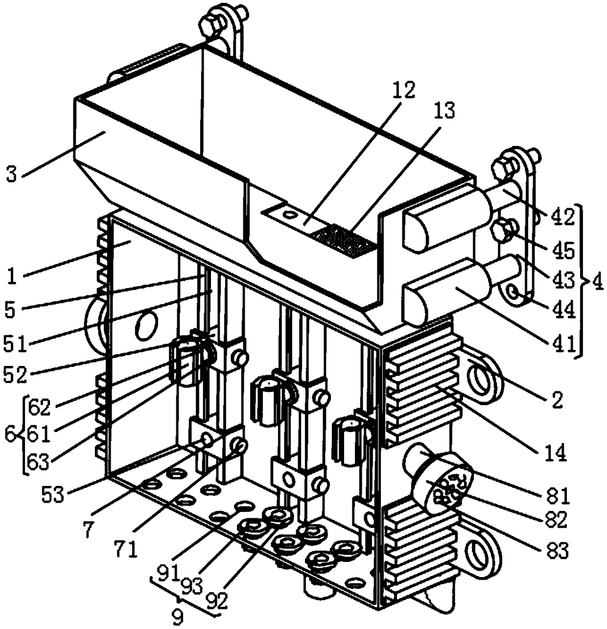
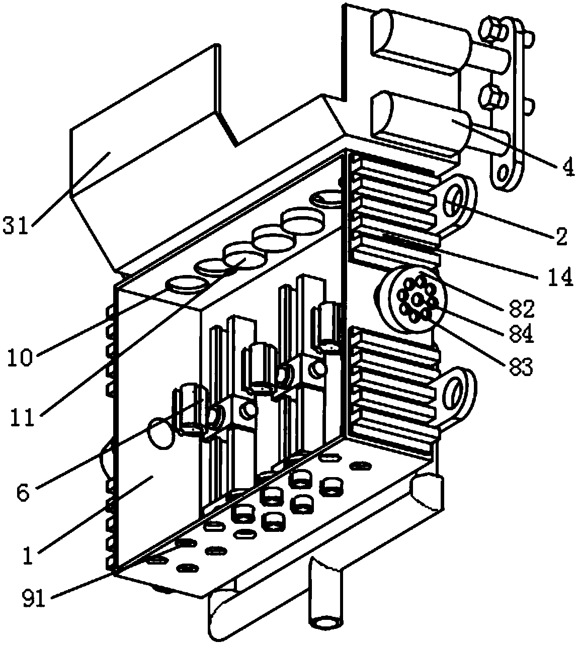
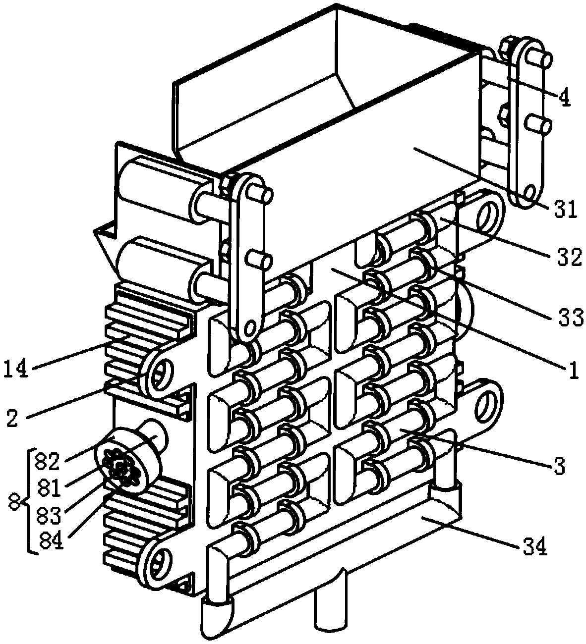
[0023] see Figure 1-3, the present invention provides a technical solution: a communication engineering optical fiber exchange box, including a box body 1, a positioning device 5 is provided on the inner surface of the box body 1, and the positioning device 5 includes a chute 51, and the chute 51 and the box body 1 The inner surface is fixedly connected, and the inside of the chute 51 is slidably provided with a slider 52, the front surface of the slider 53 i...


PUM


Abstract

The invention discloses a communication engineering optical fiber switching box. The communication engineering optical fiber switching box comprises a box body; the inner side surface of the box bodyis provided with positioning devices; the side surface of the sliding blocks of the positioning devices are provided with positioning plates; the side surfaces of the positioning plates are provided with fastening knobs; the front surfaces of the sliding blocks are provided with clamping connection devices; the lower surface of the box body is provided with a sealing device; second screw holes areuniformly distributed in the upper surface of the box body; first filtering plates are arranged in the second screw holes; the first filtering plates are of circular structures; and the side surfacesof the first filtering plates are provided with screw threads. According to the communication engineering optical fiber switching box, rainwater can be collected and filtered, and heat dissipation can be performed on the box body through the rainwater and a radiator, so that a good heat dissipation effect can be formed; the ventilation effect of the box body can be improved through a ventilationdevice; dust in the air can be filtered out through a filtering core and the first filtering plates, so that the dust and rainwater can be prevented from damaging equipment; and therefore, stable operation of the equipment can be facilitated, and the service life of the equipment can be prolonged. The communication engineering optical fiber switching box is convenient to use.

Description

technical field [0001] The invention relates to the technical field of switching boxes, in particular to a communication engineering optical fiber switching box. Background technique [0002] With the prosperity of the society and the rapid development of the network, network equipment has become an indispensable equipment in people's life. It is loved by people for its advantages of fast data transmission. The optical fiber switch box is the infrastructure of the network. A stable and fast network needs to rely on the optical fiber switch box. Many of the existing fiber optic cable switch boxes are installed outdoors, and there are many cooling holes on the fiber optic cable switch box to facilitate the cooling of the equipment running inside the switch box. However, the heat dissipation effect of the heat dissipation holes is not good, and external dust and rainwater easily enter the inside of the exchange box through the heat dissipation holes, thereby causing damage to t...

Claims


Application Information

Patent Timeline
IPC IPC(8): G02B6/44
CPCG02B6/4446
Inventor 刘东
Owner 马鞍山方融信息科技有限公司
Why Eureka
Try Eureka